Chrysler Pacifica. Manual - part 497


  Index      Chrysler     Chrysler Pacifica - service repair manual 2005 year


Search            


Content   ..  495  496  497  498   ..


Chrysler Pacifica. Manual - part 497


INSTALLATION

(1) Install the rear heated switches into the back

of the rear floor console switch bezel as required.
Make sure that the switch retaining tabs are fully
engaged to the bezel.

(2) Connect the wire harness connectors to the

rear heated seat switches.

(3) Install the rear floor console switch bezel into

the rear floor console by pushing it in through the

front surface of the console. Make sure that the bezel
retaining tabs are fully engaged to the console.

(4) Install the rear floor console (Refer to 23 -

BODY/INTERIOR/REAR

FLOOR

CONSOLE

-

INSTALLATION).

(5) Reconnect the negative battery cable.
(6) Verify 2nd row heated seat system operation.

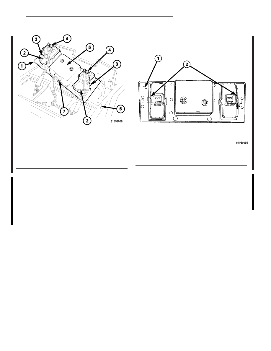
Fig. 8 Rear Floor Console Switch Bezel

1 - REAR FLOOR CONSOLE SWITCH BEZEL
2 - REAR HEATED SEAT SWITCH (2)
3 - SWITCH BEZEL RETAINING TAB (2)
4 - HEATED SEAT SWITCH WIRE CONNECTOR (2)
5 - REAR BLOWER SWITCH (INTEGRAL TO BEZEL)
6 - REAR FLOOR CONSOLE
7 - REAR BLOWER SWITCH WIRE CONNECTOR

Fig. 9 Removing 2nd Row Heated Seat Switches

1 - REAR FLOOR CONSOLE SWITCH BEZEL
2 - INSERT FLAT BLADED TOOL HERE

CS

HEATED SEAT SYSTEM

8G - 19

HEATED SEAT SWITCHES - 2ND ROW SEATS (Continued)

2005 CS Service Manual
Publication No. 81-270-05050
05CS8G-19

July, 2004

HORN

TABLE OF CONTENTS

page

page

HORN SYSTEM

DESCRIPTION

. . . . . . . . . . . . . . . . . . . . . . . . . . 1

OPERATION

. . . . . . . . . . . . . . . . . . . . . . . . . . . . 1

DIAGNOSIS AND TESTING - HORN SYSTEM

. . . 1

HORN

REMOVAL

. . . . . . . . . . . . . . . . . . . . . . . . . . . . . 1

INSTALLATION

. . . . . . . . . . . . . . . . . . . . . . . . . . 1

HORN SWITCH

DIAGNOSIS AND TESTING - HORN SWITCH

. . . 2

REMOVAL

. . . . . . . . . . . . . . . . . . . . . . . . . . . . . 2

INSTALLATION

. . . . . . . . . . . . . . . . . . . . . . . . . . 2

HORN SYSTEM

DESCRIPTION

The dual-note horn system features two electro-

magnetic horn units. The horn system includes the
following major components:

• Horn - The two horns are located on the right

side of the engine compartment near the right side
headlamp.

• Horn Switch - The horn switch is located in

the driver airbag cushion pocket, under the airbag
trim cover.

OPERATION

The horn system operates on battery current

received through a fuse in the Integrated Power
Module (IPM). The horn system circuit is designed so
that the system will remain operational, regardless
of the ignition switch position.

DIAGNOSIS AND TESTING - HORN SYSTEM

Any diagnosis of the Horn system should

begin with the use of the DRB III

diagnostic

tool. For information on the use of the DRB
III

t, refer to the appropriate Diagnostic Service

Manual.

For complete circuit diagrams, refer to the appro-

priate wiring information.

In most cases, any problem involving continually

sounding horns can be quickly alleviated by removing
the horn fuse from the Integrated Power Module
(IPM).

WARNING:

DISABLE

THE

AIRBAG

SYSTEM

BEFORE ATTEMPTING ANY STEERING WHEEL,
STEERING COLUMN, SEAT BELT TENSIONER, SIDE
AIRBAG, OR INSTRUMENT PANEL COMPONENT
DIAGNOSIS OR SERVICE. DISCONNECT AND ISO-
LATE THE BATTERY NEGATIVE (GROUND) CABLE,
THEN WAIT TWO MINUTES FOR THE AIRBAG SYS-
TEM CAPACITOR TO DISCHARGE BEFORE PER-

FORMING FURTHER DIAGNOSIS OR SERVICE. THIS
IS THE ONLY SURE WAY TO DISABLE THE AIRBAG
SYSTEM. FAILURE TO TAKE THE PROPER PRE-
CAUTIONS COULD RESULT IN ACCIDENTAL AIR-
BAG DEPLOYMENT AND POSSIBLE PERSONAL
INJURY.

HORN

REMOVAL

(1) Disconnect and isolate the battery negative

cable.

(2) Remove the mounting fasteners (Fig. 1).

(3) Disconnect the wire harness connectors.

INSTALLATION

(1) Position horns and install mounting fasteners.
(2) Connect wire harness connectors to horns.
(3) Connect battery negative cable.

Fig. 1 HORNS

1 - LOW NOTE HORN
2 - HIGH NOTE HORN

CS

HORN

8H - 1

HORN SWITCH

DIAGNOSIS AND TESTING - HORN SWITCH

Any diagnosis of the Horn system should

begin with the use of the DRB III

diagnostic

tool. For information on the use of the DRB
III

t, refer to the appropriate Diagnostic Service

Manual.

For complete circuit diagrams, refer to the appro-

priate wiring information.

WARNING:

DISABLE

THE

AIRBAG

SYSTEM

BEFORE ATTEMPTING ANY STEERING WHEEL,
STEERING COLUMN, SEAT BELT TENSIONER, SIDE
AIRBAG, OR INSTRUMENT PANEL COMPONENT
DIAGNOSIS OR SERVICE. DISCONNECT AND ISO-
LATE THE BATTERY NEGATIVE (GROUND) CABLE,
THEN WAIT TWO MINUTES FOR THE AIRBAG SYS-
TEM CAPACITOR TO DISCHARGE BEFORE PER-
FORMING FURTHER DIAGNOSIS OR SERVICE. THIS
IS THE ONLY SURE WAY TO DISABLE THE AIRBAG
SYSTEM. FAILURE TO TAKE THE PROPER PRE-
CAUTIONS COULD RESULT IN ACCIDENTAL AIR-
BAG DEPLOYMENT AND POSSIBLE PERSONAL
INJURY.

REMOVAL

WARNING: THIS SYSTEM IS A SENSITIVE, COM-
PLEX UNIT. DISCONNECT AND ISOLATE THE BAT-
TERY

NEGATIVE

CABLE

BEFORE

BEGINNING

AIRBAG

SYSTEM

COMPONENT

REMOVAL

OR

INSTALLATION PROCEDURES. THIS WILL DISABLE
THE AIRBAG SYSTEM. FAILURE TO DISCONNECT
THE BATTERY COULD RESULT IN ACCIDENTAL
AIRBAG DEPLOYMENT AND POSSIBLE PERSONAL
INJURY.
ALLOW SYSTEM CAPACITOR TO DISCHARGE FOR
TWO MINUTES BEFORE REMOVING AIRBAG COM-
PONENTS.
DO NOT PLACE AN INTACT UNDEPLOYED AIRBAG
FACE DOWN ON A SOLID SURFACE, THE AIRBAG
WILL PROPEL INTO THE AIR IF ACCIDENTALLY
DEPLOYED AND COULD RESULT IN PERSONAL
INJURY.

WHEN

CARRYING

OR

HANDLING

AN

UNDEPLOYED AIRBAG, THE TRIM SIDE OF THE
AIRBAG SHOULD BE POINTING TOWARDS THE

BODY TO MINIMIZE POSSIBILITY OF INJURY IF
ACCIDENTAL DEPLOYMENT OCCURS.

(1) Disconnect and isolate the battery negative

cable.

(2) Remove the driver’s side airbag (Refer to 8 -

ELECTRICAL/RESTRAINTS/DRIVER

AIRBAG

-

REMOVAL).

(3) Remove the airbag trim cover (Refer to 8 -

ELECTRICAL/RESTRAINTS/DRIVER

AIRBAG

-

REMOVAL).

(4) Disconnect the black wire from the air bag.
(5) Remove only the thin membrane switch from

the airbag. Do not remove the hard backer plate from
the airbag (Fig. 2).

INSTALLATION

(1) Install the horn switch to the backer plate.
(2) Connect the black wire to the airbag.
(3) Install the airbag trim cover (Refer to 8 -

ELECTRICAL/RESTRAINTS/DRIVER

AIRBAG

-

INSTALLATION).

(4) Install the driver’s airbag (Refer to 8 - ELEC-

TRICAL/RESTRAINTS/DRIVER AIRBAG - INSTAL-
LATION).

(5) Connect the battery negative cable.

Fig. 2 HORN SWITCH

1 - HORN SWITCH
2 - POWER FEED (RED WIRE)
3 - DRIVER AIRBAG
4 - GROUND WIRE (BLACK WIRE)

8H - 2

HORN

CS


Content   ..  495  496  497  498   ..