Chrysler Pacifica. Manual - part 477
INSTALLATION
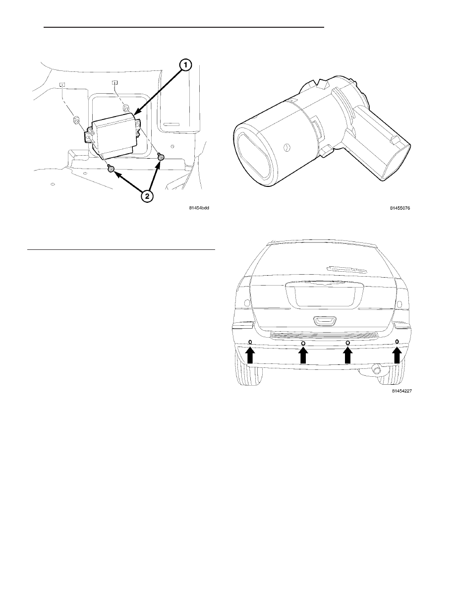
(1) Position the Park Assist Module and install the
two attaching screws (Fig. 6). Torque screws to 3.5
N·m (30 in. lbs.).
(2) Connect the Park Assist Module electrical con-
nector (Fig. 5).
(3) Install the left quarter trim panel (Refer to 23 -
BODY/INTERIOR/QUARTER
TRIM
PANEL
-
INSTALLATION).
(4) Connect the battery negative cable.
PARK ASSIST SENSOR
DESCRIPTION
The Park Assist Sensors (Fig. 7) generate ultra-
sonic pulses when triggered by the park assist mod-
ule when an obstacle is detected. The sensors then
signal the module when reflected ultrasonic pulses
are received. The sensors detect objects with an
ultrasonic pulse that reflects off the object and then
is sent to the module to determine the distance of the
object.
The Park Assist Sensors are located in the rear
bumper fascia mounted equally apart (Fig. 8).
OPERATION
The Park Assist Sensors:
• Generate ultrasonic pulses when triggered by
the Park Assist Module.
• Reception/filtering of ultrasonic energy received.
• Signalling the module of received ultrasonic
pulses that meet threshold criteria.
The sensors are supplied power by the module. The
sensor supply is enabled when the sensor function is
necessary.
The sensors detection length from the rear of the
vehicle is 0.3 meters to 1.5 meters. This area extends
around the rear side of the vehicle. The sensor detec-
tion height from the ground is 0.2 meters to about
1.5 meters.
• Ensure that the rear bumper (sensors) is free of
dirt and debris to keep the system operating prop-
erly.
• Jackhammers, large trucks, and other vibrations
could affect the performance of the system.
• Ensure that the parking brake is not applied.
If “Service Park Assist System” appears in the
EVIC after making sure the rear bumper is clean,
Fig. 6 PARK ASSIST MODULE REMOVE/INSTALL
1 - PARK ASSIST MODULE
2 - MOUNTING SCREWS
Fig. 7 PARK ASSIST SENSOR
Fig. 8 PARK ASSIST SENSOR LOCATION
CS
CHIME/BUZZER
8B - 7
PARK ASSIST MODULE (Continued)