Chrysler Stratus Convertible. Manual - part 366
ROCKER ARMS AND SHAFTS
DESCRIPTION
The rocker arms are made of light weight die-cast
with roller type follower operating against the cam-
shaft (Fig. 5). The valve actuating end of the rocker
arms are machined for hydraulic lash adjusters,
eliminating the need for periodic valve lash adjust-
ment.
The rocker arm shafts are retained by retaining
caps and bolts. Four shafts are used, one for each
intake and exhaust rocker arm assembly on each cyl-
inder head. The hollow shafts provide a duct for
lubricating oil flow from the cylinder head to the
valve mechanisms. Rocker shaft springs are use on
the intake shafts ONLY to obtain the proper clear-
ance between the intake rocker arms and the spark
plug tubes.
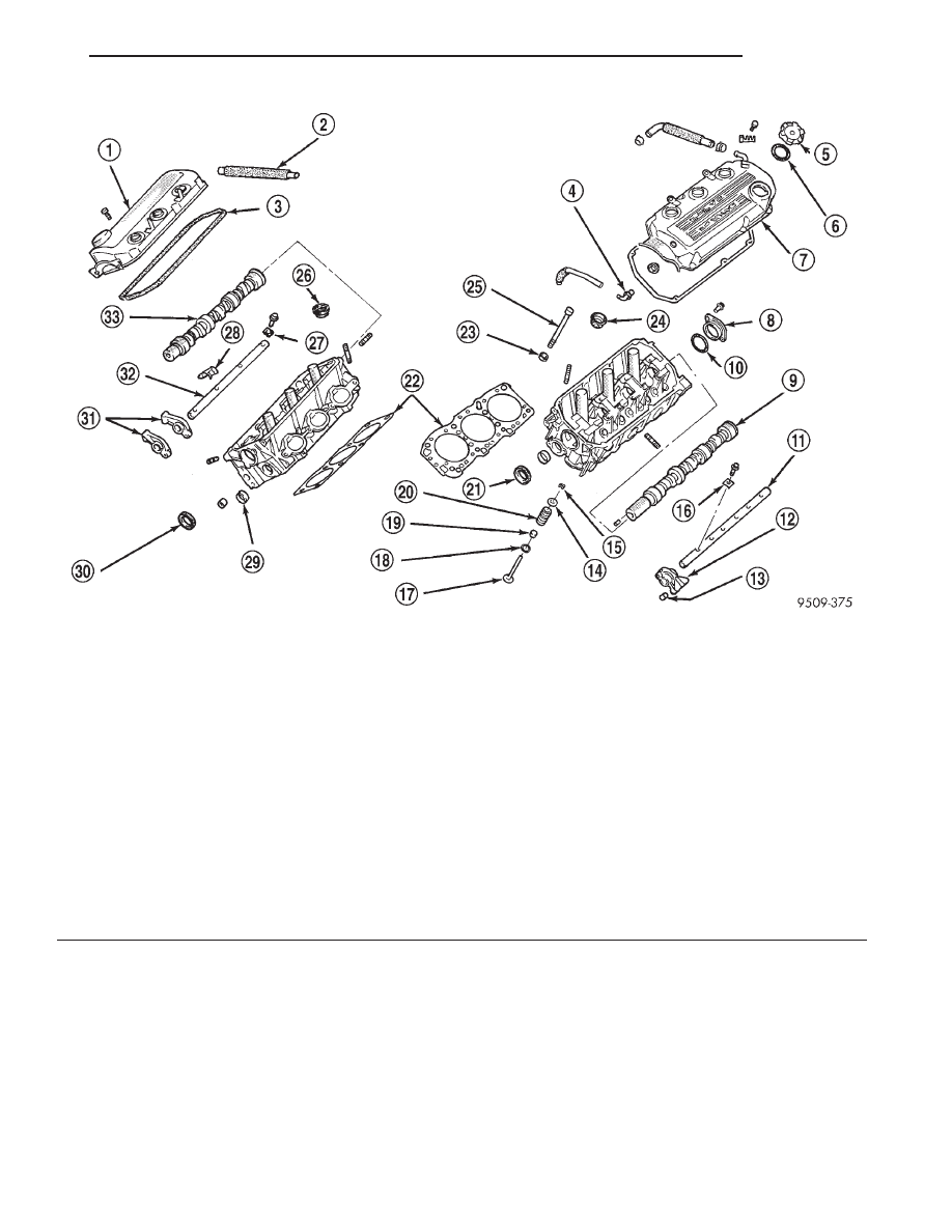
Fig. 4 Cylinder Head and Valvetrain
1 – CYLINDER HEAD COVER
2 – BREATHER HOSE
3 – GASKET
4 – PCV VALVE
5 – OIL FILLER CAP
6 – GASKET
7 – CYLINDER HEAD COVER
8 – CAMSHAFT THRUST CASE
9 – CAMSHAFT (LEFT SIDE)
10 – O-RING
11 – EXHAUST ROCKER ARM SHAFT
12 – EXHAUST ROCKER ARM
13 – HYDRAULIC LASH ADJUSTER
14 – SPRING RETAINER
15 – LOCKS
16 – CAP
17 – VALVE
18 – SPRING SEAT
19 – VALVE STEM SEAL
20 – SPRING
21 – SEAL
22 – HEAD GASKETS
23 – WASHER
24 – SEAL
25 – CYLINDER HEAD BOLT
26 – SEAL
27 – CAP
28 – SPRING
29 – CAP
30 – SEAL
31 – INTAKE ROCKER ARMS
32 – INTAKE ROCKER ARM SHAFT
33 – CAMSHAFT (RIGHT SIDE)
JX
ENGINE
9 - 5
DESCRIPTION AND OPERATION (Continued)