Chrysler Stratus Convertible. Manual - part 71
 

  Index      Chrysler     Chrysler Stratus Convertible - service repair manual 1995-2000 year


Search            


Content   ..  69  70  71  72   ..


Chrysler Stratus Convertible. Manual - part 71


Converter

housing

leaks

have

several

potential

sources. Through careful observation, a leak source
can be identified before removing the transmission
for repair.

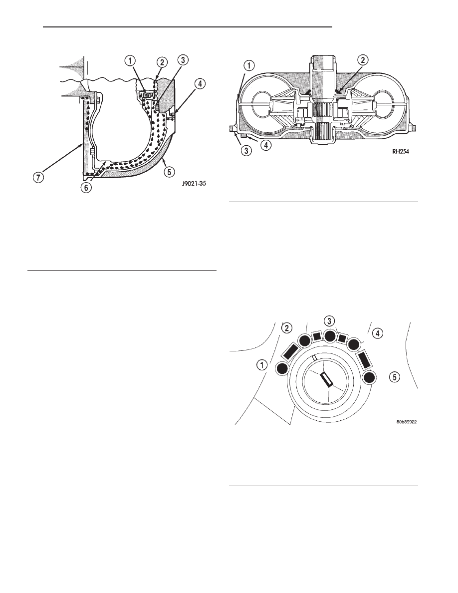
Pump seal leaks tend to move along the drive hub

and onto the rear of the converter (Fig. 29). Pump
o-ring or pump body leaks follow the same path as a
seal leak. Pump attaching bolt leaks are generally
deposited on the inside of the converter housing and
not on the converter itself. Pump seal or gasket leaks
usually travel down the inside of the converter hous-
ing (Fig. 29).

TORQUE CONVERTER LEAKAGE

Possible sources of torque converter leakage are:
• Torque converter weld leaks at the outside diam-

eter weld (Fig. 30).

• Torque converter hub weld (Fig. 30).

BRAKE/TRANSMISSION SHIFT INTERLOCK
SYSTEM

The following chart describes the normal operation

of the Brake Transmission Shift Interlock (BTSI) sys-
tem. If the “expected response” differs from the vehi-
cle’s response, then system repair and/or adjustment
is necessary.

Refer to the following chart that expected shifter

response, depending on ignition key/switch (Fig. 31)
and brake pedal positions.

Fig. 29 Converter Housing Leak Paths

1 – PUMP SEAL
2 – PUMP VENT
3 – PUMP BOLT
4 – PUMP GASKET
5 – CONVERTER HOUSING
6 – CONVERTER
7 – REAR MAIN SEAL LEAK

Fig. 30 Converter Leak Points—Typical

1 – OUTSIDE DIAMETER WELD
2 – TORQUE CONVERTER HUB WELD
3 – STARTER RING GEAR
4 – LUG

Fig. 31 Ignition Key/Switch Positions

1 – ACC
2 – LOCK
3 – OFF
4 – ON/RUN
5 – START

JX

TRANSAXLE

21 - 23

DIAGNOSIS AND TESTING (Continued)

SHIFT POSITION INDICATOR

The transmission range sensor (on the valve body)

sends a signal to the TCM on the position of the
transaxle manual valve lever. The TCM receives the
switch signal and processes the data. The TCM sends
the Shift Lever Position (SLP) information to the
BCM via the communication bus. The BCM then out-
lines the appropriate shifter position indicator in the
instrument cluster.

If a problem arises with the shifter position indica-

tor, consult the following chart for diagnostic infor-
mation. If the malfunction cannot be corrected using
the chart, consult the proper diagnostic manual.

To replace the shifter position indicator, refer to

Group 8E, Instrument Panel And Gauges.

AUTOSTICK

The autostick feature will be deactivated if one of

the following conditions occur:

• DTC

P0705–Check

Shifter

Signal–usually

accompanied by all PRNDL lights turning on in Park
and Neutral. This will result in a DTC P0705 if three
such errors are detected after any one “key–on”.

• DTC P1796–Autostick Input Circuit

• DTC P1797–Manual Shift Overheat–(Transmis-

sion oil temperature >275° F) or (Engine coolant tem-
perature >255° F).

Acceptable

powertrain

temperature

must

be

achieved to reactivate Autostick after a high temper-
ature fault:

• Transmission Oil Temperature <255° F

• Engine Coolant Temperature <240° F

SERVICE PROCEDURES

FLUID LEVEL AND CONDITION CHECK

NOTE: Only transmission fluid of the type labeled
Mopar ATF+4 (Automatic Transmission Fluid–Type
9602) should be used in this transaxle.

FLUID LEVEL CHECK

The transmission sump has a fluid level indicator

(dipstick) to check oil similar to most automatic
transmissions. It is located on the left side of the
engine. Be sure to wipe all dirt from dipstick handle
before removing.

ACTION

EXPECTED RESPONSE

1. Turn key to the “OFF”
position.

1. Shifter CAN be shifted
out of park.

2. Turn key to the

9

ON/RUN” position.

2. Shifter CANNOT be
shifted out of park.

3. Turn key to the
“ON/RUN” position and
depress the brake pedal.

3. Shifter CAN be shifted
out of park.

4. Leave shifter in any
gear and try to return key
to the “LOCK” or

9

ACC”

position.

4. Key cannot be
returned to the “LOCK” or
“ACC” position.

5. Return shifter to
“PARK” and try to remove
the key.

5. Key can be removed
(after returning to “LOCK”
position).

6. With the key removed,
try to shift out of “PARK”.

6. Shifter cannot be
shifted out of “PARK”.

NOTE: Any failure to meet these expected
responses requires system adjustment or repair.

CONDITION

POSSIBLE CAUSE

ALL PRND3L
(PRND1234 if Autostick
equipped) DISPLAY
LIGHTS “ON” IN P&N
GEAR POSITIONS

Check wiring and
connectors

Faulty TRS

Faulty manual lever

ALL DISPLAY LIGHTS
“ON” IN ALL GEAR
POSITIONS

Check wiring &
connectors

Faulty trans. range
sensor

Faulty manual lever

Communication bus
malfunction

ALL DISPLAY LIGHTS
“OFF

9

Normal transient
condition between P&R
and R&N gear positions

Check shift lever linkage

BCM malfunction

Check wiring and
connectors

Faulty instrument cluster

ALL DISPLAY LIGHTS

9

OFF” ACCOMPANIED

BY A “NO BUS”
MESSAGE

Communication bus
malfunction

DISPLAY LIGHTS OUT
OF SEQUENCE WITH
SHIFT LEVER

Check wiring and
connectors

Faulty TRS

Faulty manual lever

Communication bus
malfunction

21 - 24

TRANSAXLE

JX

DIAGNOSIS AND TESTING (Continued)

The torque converter fills in both the P Park and N

Neutral positions. Place the selector lever in P Park
to be sure that the fluid level check is accurate. The
engine should be running at idle speed for at
least one minute, with the vehicle on level
ground. 
At normal operating temperature (approxi-
mately 82 C. or 180 F.), the fluid level is correct if it
is in the HOT region (cross-hatched area) on the oil
level indicator (Fig. 32). The fluid level will be
approximately one-quarter inch above the lower hole
of the dipstick at 70° F fluid temperature.

FLUID LEVEL CHECK USING DRB

NOTE: Engine and Transaxle should be at normal
operating temperature before performing this proce-
dure.

(1) Start engine and apply parking brake.
(2) Hook up DRB scan tool and select transmis-

sion.

(3) Select sensors.
(4) Read the transmission temperature value.
(5) Compare the fluid temperature value with the

chart.

(6) Adjust transmission fluid level shown on the

dipstick according to the chart.

(7) Check transmission for leaks.
Low fluid level can cause a variety of conditions

because it allows the pump to take in air along with
the fluid. As in any hydraulic system, air bubbles
make the fluid spongy, therefore, pressures will be
low and build up slowly.

Improper filling can also raise the fluid level too

high. When the transaxle has too much fluid, the
gears churn up foam and cause the same conditions
which occur with a low fluid level.

In either case, air bubbles can cause overheating

and/or fluid oxidation, and varnishing. This can
interfere with normal valve, clutch, and accumulator

operation. Foaming can also result in fluid escaping
from the transaxle vent where it may be mistaken
for a leak.

FLUID CONDITION

Along with fluid level, it is important to check the

condition of the fluid. When the fluid smells burned,
and is contaminated with metal or friction material
particles, a complete transaxle recondition is needed.
Be sure to examine the fluid on the dipstick closely.
If there is any doubt about its condition, drain out a
sample for a double check.

Mopar

t ATF+4 (Automatic Transmission Fluid-

Type 9602) when new is red in color. The ATF is dyed
red so it can be identified from other fluids used in
the vehicle such as engine oil or antifreeze. The red
color is not permanent and is not an indicator of fluid
condition. As the vehicle is driven, the ATF will begin
to look darker in color and may eventually become
brown. This is normal. A dark brown/black fluid
accompanied with a burnt odor and/or deterioration
in shift quality may indicate fluid deterioration or
transmission component failure.

After the fluid has been checked, seat the dipstick

fully to seal out water and dirt.

TRANSAXLE FLUID AND FILTER SERVICE

NOTE: Refer

to

the

maintenance

schedules

in

Group 0, Lubrication and Maintenance, or the vehi-
cle owner’s manual, for the recommended mainte-
nance

(fluid/filter

change)

intervals

for

this

transaxle.

NOTE: Only fluids of the type labeled Mopar

T

ATF+4 (Automatic Transmission Fluid) Type 9602
should be used. A filter change should be made at
the time of the transmission oil change. The magnet
(on the inside of the oil pan) should also be cleaned
with a clean, dry cloth.

NOTE: If the transaxle is disassembled for any rea-
son, the fluid and filter should be changed.

FLUID/FILTER SERVICE (RECOMMENDED)

(1) Raise vehicle on a hoist (See Lubrication,

Group 0). Place a drain container with a large open-
ing, under transaxle oil pan.

(2) Loosen pan bolts and tap the pan at one corner

to break it loose allowing fluid to drain, then remove
the oil pan.

(3) Install a new filter and o-ring on bottom of the

valve body (Fig. 33).

Fig. 32 Fluid Level Indicator Markings

1 – TRANSAXLE DIPSTICK

JX

TRANSAXLE

21 - 25

SERVICE PROCEDURES (Continued)

(4) Clean the oil pan and magnet. Reinstall pan

using new Mopar Silicone Adhesive sealant. Tighten
oil pan bolts to 19 N·m (165 in. lbs.).

(5) Pour four quarts of Mopar

t ATF+4 (Automatic

Transmission Fluid) Type 9602 through the dipstick
opening.

(6) Start engine and allow to idle for at least one

minute. Then, with parking and service brakes
applied, move selector lever momentarily to each
position, ending in the park or neutral position.

(7) Check the transaxle fluid level and add an

appropriate amount to bring the transaxle fluid level
to 3mm (1/8 in.) below the “ADD” mark on the dip-
stick (Fig. 34).

Transmission Fluid Temperature Chart

Fig. 33 Filter and O-Ring

1 – OIL FILTER
2 – O-RING

Fig. 34 Dipstick Markings

1 – TRANSAXLE DIPSTICK

21 - 26

TRANSAXLE

JX

SERVICE PROCEDURES (Continued)


Content   ..  69  70  71  72   ..