Chrysler Stratus Convertible. Manual - part 23
 

  Index      Chrysler     Chrysler Stratus Convertible - service repair manual 1995-2000 year


Search            


Content   ..  21  22  23  24   ..


Chrysler Stratus Convertible. Manual - part 23


CAUTION: The interior components (O-rings, spac-
ers, retainers) of this type of quick-connect fitting
are not serviced separately. Do not attempt to repair
damaged fittings or fuel lines/tubes. If repair is nec-
essary, replace the complete fuel tube assembly.

WARNING: THE FUEL SYSTEM IS UNDER A CON-
STANT PRESSURE (EVEN WITH THE ENGINE OFF).
BEFORE SERVICING ANY FUEL SYSTEM HOSES,
FITTINGS OR LINES, THE FUEL SYSTEM PRES-
SURE MUST BE RELEASED. REFER TO THE FUEL
SYSTEM PRESSURE RELEASE PROCEDURE IN
THIS GROUP.

DISCONNECTION/CONNECTION

(1) Perform fuel pressure release procedure. Refer

to Fuel Pressure Release Procedure in this section.

(2) Disconnect negative battery cable from battery

or auxiliary jumper terminal.

(3) Clean fitting of any foreign material before dis-

assembly.

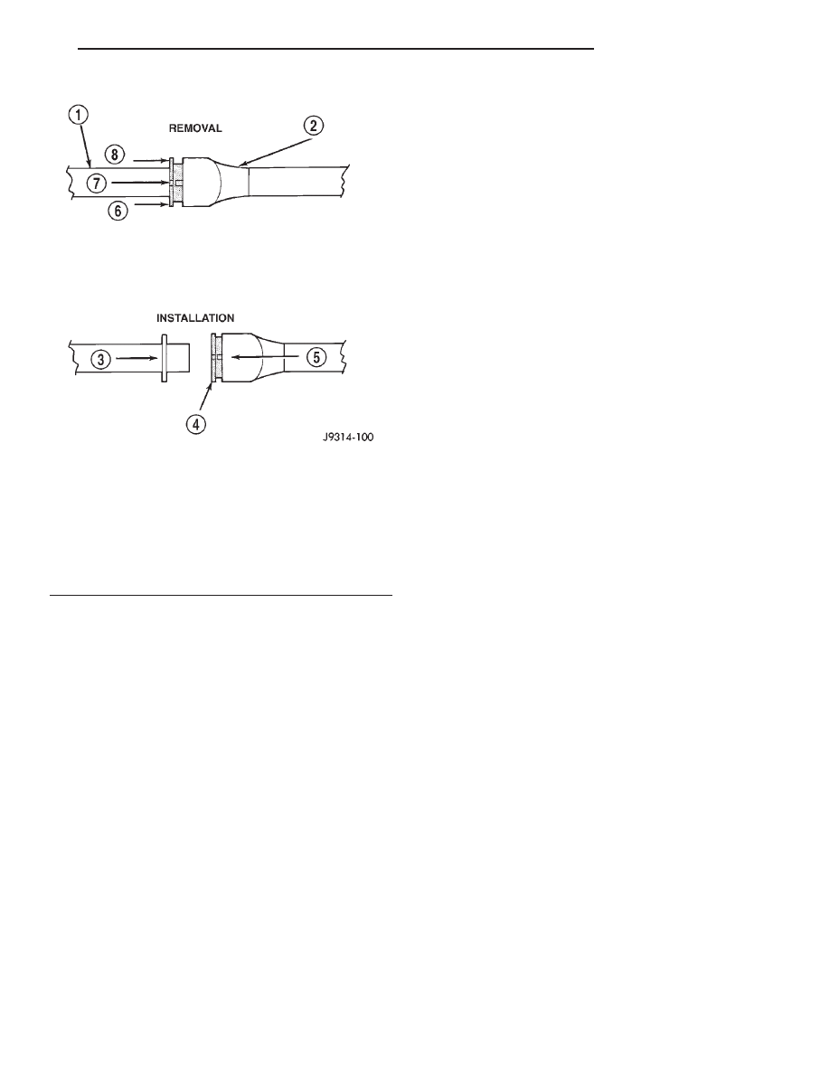
(4) To release fuel system component from quick-

connect fitting, firmly push fitting towards compo-

nent being serviced while firmly pushing plastic
retainer ring into fitting (Fig. 9). With plastic ring
depressed, pull fitting from component. The plastic
retainer ring must be pressed squarely into fit-
ting body. If this retainer is cocked during
removal, it may be difficult to disconnect fit-
ting. Use an open-end wrench on shoulder of
plastic retainer ring to aid in disconnection.

(5) After disconnection, plastic retainer ring will

remain with quick-connect fitting connector body.

(6) Inspect fitting connector body, plastic retainer

ring and fuel system component for damage. Replace
as necessary.

(7) Prior to connecting quick-connect fitting to

component being serviced, check condition of fitting
and component. Clean parts with a lint-free cloth.
Lubricate with clean engine oil.

(8) Insert quick-connect fitting into component

being serviced until a click is felt.

(9) Verify a locked condition by firmly pulling on

fuel tube and fitting (15-30 lbs.).

(10) Connect negative battery cable to battery or

auxiliary jumper terminal.

(11) Use the DRB scan tool ASD Fuel System Test

to pressurize the fuel system. Check for leaks.

REMOVAL AND INSTALLATION

AUTOMATIC SHUTDOWN RELAY

The relay is located in the Power Distribution Cen-

ter (PDC) (Fig. 10). For the location of the relay
within the PDC, refer to the PDC cover for location.
Check electrical terminals for corrosion and repair as
necessary.

FUEL PUMP RELAY

The fuel pump relay is located in the PDC (Fig.

10). The inside top of the PDC cover has a label
showing relay and fuse location.

FUEL PUMP MODULE

WARNING: RELEASE FUEL SYSTEM PRESSURE
BEFORE SERVICING FUEL SYSTEM COMPONENTS.
SERVICE VEHICLES IN WELL VENTILATED AREAS
AND AVOID IGNITION SOURCES. NEVER SMOKE
WHILE SERVICING THE VEHICLE.

REMOVAL

(1) Remove fuel filler cap and perform Fuel Sys-

tem Pressure Release procedure.

(2) Disconnect

negative

cable

from

auxiliary

jumper terminal.

(3) Remove fuel tank, refer to the Fuel Tank

removal section.

Fig. 9 Plastic Retainer Ring Type Fitting

1 – FUEL TUBE
2 – QUICK CONNECT FITTING
3 – PUSH
4 – PLASTIC RETAINER
5 – PUSH
6 – PUSH
7 – PUSH
8 – PUSH

JX

FUEL SYSTEM

14 - 9

SERVICE PROCEDURES (Continued)

(4) Disconnect fuel filter lines from fuel pump

module.

(5) Clean top of tank to remove loose dirt and

debris.

(6) Using Special Tool #6856 Fuel Pump Module

Ring Spanner, remove locknut to release pump mod-
ule (Fig. 11).

WARNING:

THE FUEL RESERVOIR OF THE FUEL

PUMP MODULE DOES NOT EMPTY OUT WHEN THE
TANK IS DRAINED. THE FUEL IN THE RESERVOIR
MAY SPILL OUT WHEN THE MODULE IS REMOVED.

(7) Remove fuel pump module and O-ring from

tank (Fig. 12). Discard O-ring.

INSTALLATION

(1) Wipe seal area of tank clean. Place a new

O-ring on the ledge between the tank threads and
the pump module opening.

(2) Position fuel pump module in tank. Make sure

the alignment tab on the underside of the pump mod-
ule flange sits in the corresponding notch in the fuel
tank.

CAUTION: Over tightening the pump lock ring may
result in a leak.

(3) While holding the pump module in position,

install locknut. Tighten locknut to 74.5 N·m (55 ft.
lbs) torque using special tool #6856.

(4) Install fuel tank and fuel filter, refer to the

Fuel Tank installation section.

(5) Install negative cable to auxiliary jumper ter-

minal.

(6) Fill fuel tank with clean fuel. Use the DRB

scan tool to pressurize the system and check for
leaks.

Fig. 10 Power Distribution Center (PDC)

1 – BATTERY POSITIVE
2 – BATTERY GROUND
3 – AIR CLEANER
4 – PCM
5 – PDC
6 – TCM

Fig. 11 Fuel Pump Module Locknut

1 – SPECIAL TOOL 6856
2 – FUEL PUMP MODULE LOCK RING

Fig. 12 Fuel Pump Module Removal

1 – FUEL PUMP MODULE
2 – O-RING

14 - 10

FUEL SYSTEM

JX

REMOVAL AND INSTALLATION (Continued)

FUEL FILTER

The fuel filter mounts to the frame above the rear

of the fuel tank. The inlet and outlet tubes are per-
manently attached to the filter.

REMOVAL

WARNING: RELEASE FUEL SYSTEM PRESSURE
BEFORE DISCONNECTING QUICK- CONNECT FIT-
TINGS AT FUEL FILTER AND FUEL PUMP MODULE.
REFER TO THE FUEL PRESSURE RELEASE PRO-
CEDURE

(1) Remove rear seat.
(2) Disconnect fuel pump electrical connector. Push

grommet out and feed jumper completely through
hole in body.

(3) Remove fuel cap slowly to release tank pres-

sure.

(4) With vehicle on a hoist, drain fuel from tank.

Refer to Fuel Tank Draining in this section.

(5) Remove driver’s side fuel tank strap. Loosen,

do not remove, passenger side fuel tank strap allow-
ing fuel tank fill neck to touch rear suspension cross-
member.

WARNING: WRAP SHOP TOWELS AROUND HOSES
TO CATCH ANY GASOLINE SPILLAGE.

(6) Disconnect fuel lines from fuel pump module

(Fig. 13). These are quick connect fittings. Refer to
Quick Connect Fittings in this section.

(7) Disconnect fuel supply line from the fuel brake

module.

(8) Remove fuel filter (Fig. 14).

INSTALLATION

The fuel supply (to filter) tube, return tube (to

pump module) are permanently attached to the fuel
filter. The ends of the fuel supply and return tubes
have different size quick-connect fittings. The larger
quick-connect fitting connects to the large nipple
(supply side) on the fuel pump module. The smaller
quick-connect fitting attaches to the small nipple
(return side) on the fuel pump module.

(1) Apply a light coating of clean 30 weight engine

oil to the fuel filter nipples. Install fuel tubes. Refer
to Fuel Tubes and Quick-Connect Fittings in this sec-
tion.

(2) Install fuel tank, filter and tank straps, install

the front bolts first and then the rear bolts. Torque
tank strap bolts to 23 N·m (250. in. lbs.). Make sure
pump module harness grommet is installed in
body as tank is raised into position.

(3) Lower vehicle and connect pump module con-

nector.

(4) Install rear seat.
(5) Fill tank with fuel.
(6) Connect negative cable to auxiliary jumper ter-

minal.

(7) Use the DRB scan tool ASD Fuel system test to

pressurize the the fuel system. Check for leaks.

FUEL PRESSURE REGULATOR

The fuel pressure regulator is part of the fuel

pump module (Fig. 15). Remove the fuel pump mod-
ule from the fuel tank to access the fuel pressure reg-
ulator. Refer to the Fuel Pump Module removal in
this section.

Fig. 13 Fuel Lines at Fuel Pump Module

1 – FUEL LINES
2 – FUEL PUMP MODULE LOCK RING
3 – FUEL FILTER

Fig. 14 Fuel Filter

1 – REAR CROSSMEMBER
2 – FUEL FILTER
3 – FUEL FILL NECK

JX

FUEL SYSTEM

14 - 11

REMOVAL AND INSTALLATION (Continued)

WARNING: FUEL SYSTEM PRESSURE MUST BE
RELEASED BEFORE SERVICING ANY FUEL SYS-
TEM COMPONENT. PERFORM THE FUEL SYSTEM
PRESSURE RELEASE PROCEDURE.

REMOVAL

(1) Spread tangs on pressure regulator retainer

(Fig. 15).

(2) Pry fuel pressure regulator out of housing.
(3) Ensure both upper and lower O-rings were

removed with regulator.

INSTALLATION

(1) Lightly lubricate the O-rings with clean engine

oil and place them into opening in pump module (Fig.
16).

(2) Push regulator into opening in pump module.
(3) Fold tangs on regulator retainer over tabs on

housing.

(4) Install Fuel Pump Module, refer to the Fuel

Pump Module installation in this section.

FUEL PUMP INLET STRAINER

REMOVAL

(1) Remove fuel pump module. Refer to Fuel Pump

Module Removal in this section.

(2) Using a thin straight blade screwdriver, care-

fully pry back the locking tabs on fuel pump reser-
voir and remove the strainer (Fig. 17).

(3) Remove strainer O-ring from the fuel pump

reservoir body.

(4) Remove any contaminants by washing the

inside of the fuel tank.

INSTALLATION

(1) Lubricate the strainer O-ring with clean motor

oil.

(2) Insert strainer O-ring into outlet of strainer so

that it sits evenly on the step inside the outlet.

(3) Push strainer onto the inlet of the fuel pump

reservoir body. Make sure the locking tabs on the
reservoir body lock over the locking tangs on the
strainer.

(4) Install fuel pump module. Refer to Fuel Pump

Module Installation in this section.

Fig. 15 Fuel Pressure Regulator

1 – PRY BETWEEN REGULATOR AND HOUSING
2 – FUEL PRESSURE REGULATOR
3 – TABS (4)

Fig. 16 Fuel Pressure Regulator O-rings

1 – UPPER O-RING
2 – LOWER O-RING

Fig. 17 Inlet Strainer Removal

1 – TABS
2 – INLET STRAINER

14 - 12

FUEL SYSTEM

JX

REMOVAL AND INSTALLATION (Continued)


Content   ..  21  22  23  24   ..