Chrysler Stratus Convertible. Manual - part 8
 

  Index      Chrysler     Chrysler Stratus Convertible - service repair manual 1995-2000 year


Search            


Content   ..  6  7  8  9   ..


Chrysler Stratus Convertible. Manual - part 8


(5) Install rear wheelhouse splash shields.
(6) Connect license plate lamp wire connector.
(7) Install push-in fasteners attaching rear fascia

to rear bumper reinforcement.

(8) Install nuts attaching rear fascia to inner quar-

ter panel.

(9) Install screws attaching rear fascia to closure

panel.

(10) Install trunk lining.

REAR BUMPER REINFORCEMENT

REMOVAL

(1) Remove rear fascia.
(2) Support bumper reinforcement on a suitable

lifting device.

(3) Mark position of nuts on frame rail to aid in

installation.

(4) Remove nuts holding rear bumper reinforce-

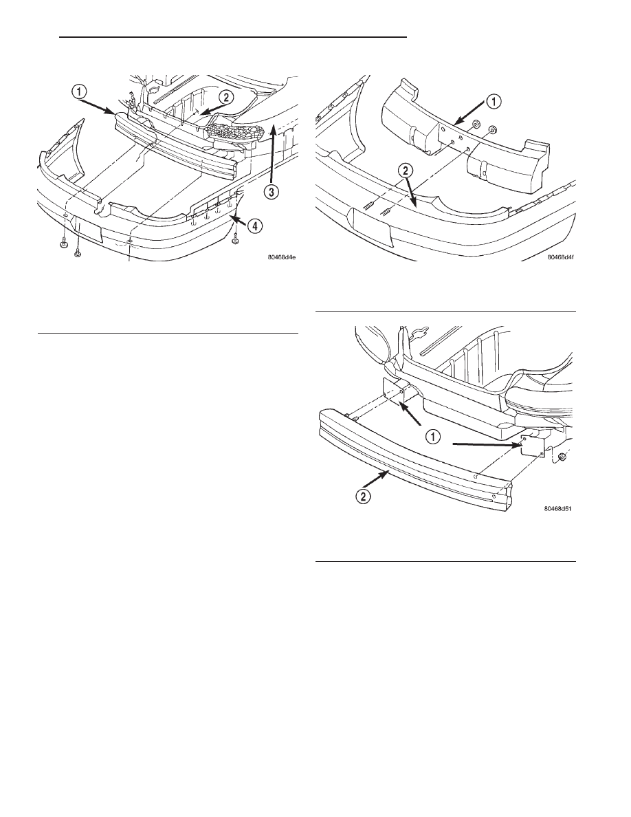
ment to frame rail (Fig. 6).

(5) Separate bumper reinforcement from vehicle.

INSTALLATION

(1) Position rear bumper reinforcement on vehicle.

(2) Install nuts holding bumper reinforcement to

frame rail. Use previously made marks to properly
position bumper reinforcement.

(3) Install rear fascia.

Fig. 4 Rear Bumper Fascia

1 – REAR BUMPER REINFORCEMENT
2 – TRUNK
3 – QUARTER PANEL
4 – REAR BUMPER FASCIA

Fig. 5 Rear Bumper Energy Management Foam

1 – ENERGY MANAGEMENT FOAM
2 – REAR BUMPER FASCIA

Fig. 6 Rear Bumper Reinforcement

1 – FRAME RAIL
2 – FRONT BUMPER REINFORCEMENT

JX

FRAME AND BUMPERS

13 - 3

REMOVAL AND INSTALLATION (Continued)

FRAME

TABLE OF CONTENTS

page

page

DESCRIPTION AND OPERATION

REAR SUSPENSION CROSSMEMBER . . . . . . . . . 4

REMOVAL AND INSTALLATION

FRONT SUSPENSION CROSSMEMBER . . . . . . . . 4

REAR SUSPENSION CROSSMEMBER . . . . . . . . . 5

SPECIFICATIONS

FRAME DIMENSIONS . . . . . . . . . . . . . . . . . . . . . . 7
TORQUE SPECIFICATIONS . . . . . . . . . . . . . . . . . . 8

DESCRIPTION AND OPERATION

REAR SUSPENSION CROSSMEMBER

DESCRIPTION

This vehicle is equipped with a bolt in type rear

suspension crossmember. The crossmember on this
vehicle is the same for all of the optional suspensions
that are available on the vehicle.

REMOVAL AND INSTALLATION

FRONT SUSPENSION CROSSMEMBER

REMOVAL

(1) Hoist and support vehicle on safety stands.

Refer to Group 0, Lubrication and Maintenance, for
proper procedure.

(2) Place a suitable lifting device under front sus-

pension crossmember.

(3) Remove bolts holding suspension strut to the

lower control arm. Refer to Group 2, Suspension, for
proper procedures.

(4) Disengage lower ball joints from lower control

arms. Refer to Group 2, Suspension, for proper pro-
cedures.

(5) Remove bolts holding front of suspension cross-

member to frame rails under upper control arms.

(6) Loosen bolts holding rear of suspension cross-

member to frame rail torque boxes.

(7) Allow the front of the suspension crossmember

to swing away from the frame rails.

(8) Remove bolts holding steering gear to top of

suspension crossmember (Fig. 1).

CAUTION: Do not allow steering gear to hang by
the pressure or return hoses, damage to hoses can
result.

(9) Using mechanics wire, tie steering gear to

structure above.

(10) Raise crossmember back into position.

(11) Remove bolts holding rear of crossmember to

frame rail torque boxes.

(12) Lower front suspension crossmember away

from bottom of vehicle.

INSTALLATION

(1) Raise front suspension crossmember into posi-

tion on vehicle.

(2) Loosely install bolts holding rear of crossmem-

ber to frame rail torque boxes.

(3) Lower crossmember and install bolts holding

steering gear to top of suspension crossmember.

(4) Raise crossmember into position.
(5) Tighten bolts holding rear of suspension cross-

member to frame rail torque boxes.

(6) Install bolts holding front of suspension cross-

member to frame rails under upper control arm.

Fig. 1 Front Suspension Crossmember

1 – STEERING GEAR
2 – FRONT SUSPENSION CROSSMEMBER
3 – CLAMP
4 – ISOLATOR

13 - 4

FRAME AND BUMPERS

JX

(7) Engage lower ball joint to lower control arms.

Refer to Group 2, Suspension, for proper procedures.

(8) Install bolts holding suspension strut to lower

control arm. Refer to Group 2, Suspension, for proper
procedures.

REAR SUSPENSION CROSSMEMBER

REMOVE

(1) Raise vehicle on jackstands or centered on a

frame contact type hoist. See Hoisting in the Lubri-
cation and Maintenance section of this manual, for
the required lifting procedure to be used for this
vehicle.

(2) Remove both rear wheel and tire assemblies

from the vehicle.

(3) Remove the shock absorber clevis bracket to

rear knuckle attaching bolt and nut on both sides of
the vehicle (Fig. 2).

(4) Remove muffler support bracket from rear

frame rail (Fig. 3).

(5) Remove the rear exhaust pipe hanger from the

rear

suspension

crossmember

(Fig.

4).

Let

the

exhaust system drop down as far as possible.

(6) Position a transmission jack and wooden block

under the center of the rear suspension crossmember
to support and lower crossmember during removal
(Fig. 5).

(7) Remove the routing clips for the wheel speed

sensor cable from the brackets on the upper control
arm (Fig. 6).

(8) Remove the nuts and bolts on each side of the

vehicle attaching the 4 lateral links to the knuckles.

(9) Remove the 4 bolts attaching the rear suspen-

sion crossmember to the rear frame rails (Fig. 7).

(10) Lower

the

rear

suspension

crossmember

enough to access the upper control arm pivot bar to
crossmember attaching bolts (Fig. 8).

Fig. 2 Shock Absorber To Knuckle Attaching

1 – ATTACHING BOLT
2 – REAR KNUCKLE
3 – SHOCK ABSORBER CLEVIS BRACKET
4 – LATERAL LINK

Fig. 3 Muffler Support Bracket

1 – REAR FASCIA
2 – MUFFLER SUPPORT BRACKET
3 – ATTACHING BOLTS
4 – MUFFLER

Fig. 4 Exhaust Pipe Hanger At Rear Suspension

Crossmember

1 – BOLT
2 – REAR SUSPENSION CROSSMEMBER
3 – HANGER BRACKET
4 – EXHAUST PIPE

JX

FRAME AND BUMPERS

13 - 5

REMOVAL AND INSTALLATION (Continued)

NOTE: One flat washer is used at each upper con-
trol arm pivot bar attaching bolt. The flat washer is
located between the pivot bar and the rear suspen-
sion crossmember. Be sure the washers are not
lost when removing the pivot bar attaching bolts
from the rear suspension crossmember.

(11) Remove the 4 bolts (Fig. 8) attaching the

upper control arm pivot bars to the rear suspension
crossmember. Remove the control arms from the
crossmember.

(12) Lower the rear suspension crossmember, lateral

arms and stabilizer bar as far as possible using the
transmission jack. Then with the aid of a helper remove
rear suspension crossmember from the vehicle.

(13) Transfer

the

lateral

arms,

stabilizer

bar

mounting brackets and the stabilizer bar and bush-

Fig. 5 Lowering And Supporting Rear Suspension

Crossmember

1 – WOODEN BLOCK
2 – TRANSMISSION JACK
3 – REAR SUSPENSION CROSSMEMBER

Fig. 6 Speed Sensor Cable Attachment To Control

Arm

1 – UPPER CONTROL ARM
2 – SHOCK ABSORBER
3 – SPEED SENSOR CABLE ROUTING CLIPS
4 – BOLT
5 – SPEED SENSOR CABLE
6 – BRAKE FLEX HOSE BRACKET
7 – BOLT
8 – BRAKE DRUM

Fig. 7 Suspension Crossmember Attachment To

Frame Rails

1 – ATTACHING BOLTS
2 – ATTACHING BOLTS
3 – REAR SUSPENSION CROSSMEMBER

Fig. 8 Upper Control Arm Attachment To

Crossmember

1 – SHOCK ABSORBER
2 – ATTACHING BOLTS
3 – UPPER CONTROL ARM PIVOT BAR
4 – REAR SUSPENSION CROSSMEMBER
5 – UPPER CONTROL ARM

13 - 6

FRAME AND BUMPERS

JX

REMOVAL AND INSTALLATION (Continued)


Content   ..  6  7  8  9   ..