Chrysler New Yorker. Manual - part 519
 

  Index      Chrysler     Chrysler New Yorker - service repair manual 1997-1999 year


Search            


Content   ..  517  518  519  520   ..


Chrysler New Yorker. Manual - part 519


TEST 14A

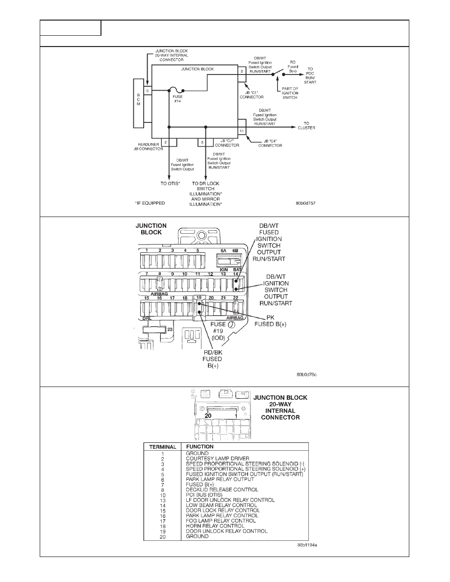
CONTINUED - REPAIRING FUSED IGNITION SWITCH OUTPUT TO BCM

FIG. 1

FIG. 2

V
E

H

I

C

L

E

C

O

M
M

U
N

I

C
A

T

I

O

N

674

TEST 14A

CONTINUED - REPAIRING FUSED IGNITION SWITCH OUTPUT TO BCM

*Perform Verification TEST VER-2A.

**Check connectors - Clean / repair as necessary.

TEST 14A

KEY ON. USING A

REPAIR THE OPEN 

CONTINUED FROM 

VOLTMETER, MEASURE

IS THE VOLTAGE

NO 

IGN SWITCH OUTPUT 

THE PREVIOUS 

THE IGNITION SWITCH 

ABOVE 10.0 VOLTS? 

CKT FROM IGNITION 

PAGE.

OUTPUT CKT AT FUSE 

SWITCH TO THE

#14. FIG. 1

JUNCTION BLOCK.*

YES

KEY OFF. 

ENSURE THAT ALL

REINSTALL FUSE 

REMOVE THE BODY 

JUNCTION BLOCK

#14. CONTROL MODULE 

CONNECTORS 

ARE

FROM THE JUNCTION 

STILL CONNECTED. 

BLOCK. 

USING A VOLTMETER, 

TURN IGNITION ON 

MEASURE THE FUSED

IS THE VOLTAGE

NO 

REPLACE THE

(ENGINE OFF).

IGNITION SWITCH 

ABOVE 10.0 VOLTS? 

JUNCTION BLOCK.*

OUTPUT CKT (CAV 5).

FIG. 2

YES

REPLACE THE BODY 
CONTROL MODULE.* 

V
E

H

I

C

L

E

C

O

M
M

U
N

I

C
A

T

I

O

N

675

TEST 1A

IDENTIFYING VEHICLE THEFT SECURITY SYSTEM PROBLEMS

Perform TEST SYMPTOM IDENTIFICATION 1A Before Proceeding

V
E

H

I

C

L

E

T

H

E

F
T

S
E

C
U
R

I

T

Y

S
Y
S

T

E

M

676

TEST 1A

IDENTIFYING VEHICLE THEFT SECURITY SYSTEM PROBLEMS

Perform TEST SYMPTOM IDENTIFICATION 1A Before Proceeding

For complaints about the Theft Alarm going off on its own use the DRB and select ‘‘Theft Alarm’’ then
‘‘Monitor Display’’ and read the ‘‘Alarmed Tripped By’’ status.

Verify the failure or customer’s complaint and make sure the vehicle is experiencing the problem at
this time.

NOTE: If the VTSS indicator lamp stays on constantly, 30 seconds after the key is turned on, or while
driving . . . . . . . . . . . . . . . . . . . . . . . . . . . . . . . . . . . . . . . . . . . . . . . . . . . . . . . . . . . .perform TEST 3A.

1. With the DRB, select ‘‘Body’’, ‘‘Body Computer’’. Verify Communication with the Body

Controller, if ‘‘No Response’’ . . . . . . . . . . . . . . . .perform ‘‘Vehicle Communication’’ TEST 1A.

2. With the DRB, select ‘‘Monitor Display’’ to read the vehicle theft security status. If the VTSS

mode is not ‘‘Disarmed’’ . . . . . . . . . . . . . . . . . . . . . . . . . . . . . . . . . . . . . . . . .perform TEST 2A.

3. With the DRB, select ‘‘Sensors’’ and read the ‘‘Ignition Voltage’’. If it does not show battery

voltage with the key on. . . . . . . . . . . . . . . . . . . .perform ‘‘Vehicle Communication’’ TEST 14A.

4. With the DRB, verify the ‘‘Key in Ignition Switch’’ state is closed with the key in the ignition, if

it is not . . . . . . . . . . . . . . . . . . . . . . . . . . . . . . . . . . . . . .perform ‘‘Power Door Locks’’ TEST 9A.

5. With the DRB, select ‘‘Miscellaneous’’, ‘‘Change Mode’’, and ‘‘Diagnostics’’ to put the theft

alarm in diagnostic mode, then follow the directions on the DRB screen.

When entering the diagnostic mode with the key in the ignition, the horn should sound twice
and the headlights and VTSS indicator should flash.

− If the horn fails to sound . . . . . . . . . . . . . . . . . . . . . . . . . . . . . . . . . . . . . . .perform TEST 4A.
− If the VTSS indicator lamp fails to flash . . . . . . . . . . . . . . . . . . . . . . . . . . .perform TEST 5A.
− If the headlamps/park lamps fail to flash . . . . . . . . . . .perform “Exterior Lighting” TEST 1A.

6. Remove the key from the ignition switch. Perform each action and if the horn doesn’t sound

after each action, perform the test indicated below.

Open and close the left front door . . . . . . . . . . . . . . . . . . . . . . . .perform “Door Ajar” TEST 1A
Open and close the right front door . . . . . . . . . . . . . . . . . . . . . . .perform “Door Ajar” TEST 1A
Open and close the right rear door. . . . . . . . . . . . . . . . . . . . . . . .perform “Door Ajar” TEST 1A
Open and close the left rear door. . . . . . . . . . . . . . . . . . . . . . . . .perform “Door Ajar” TEST 1A
Rotate the key in the left front door key cylinder . . . . .perform “Power Door Locks” TEST 1A
Rotate the key in the right front door key cylinder . . . .perform “Power Door Locks” TEST 1A

7. Turn the ignition to the ‘‘On’’ position. If the horn fails

to sound. . . . . . . . . . . . . . . . . . . . . . . . . . . . . . . . .perform ‘‘Vehicle Communication’’ TEST 1A.

8. With the DRB, select ‘‘Monitor Display’’ to read the VTSS status. If the VTSS mode is not

‘‘Disarmed’’, or engine controller is not ‘‘OK to arm/OK to run engine’’, perform the test indicated
below.

− If the VTSS mode is other than disarmed . . . . . . . . . . . . . . . . . . . . . . . . . . . . . . . . .TEST 2A
− If engine controller is ‘‘1 No Response/

2 No Response’’ . . . . . . . . . . . . . . . . . . . . . . . . .perform “Vehicle Communication” TEST 8A

− If engine controller is ‘‘1 Not OK to Arm VTSS/2 OK to run Engine’’ . . . . .replace the PCM.

9. If there is a problem with the remote keyless entry arm/disarm function.perform “Power Door

Locks” TEST 11A.

V
E

H

I

C

L

E

T

H

E

F
T

S
E

C
U
R

I

T

Y

S
Y
S

T

E

M

677


Content   ..  517  518  519  520   ..