Chrysler New Yorker. Manual - part 286


  Index      Chrysler     Chrysler New Yorker - service repair manual 1997-1999 year


Search            


Content   ..  284  285  286  287   ..


Chrysler New Yorker. Manual - part 286


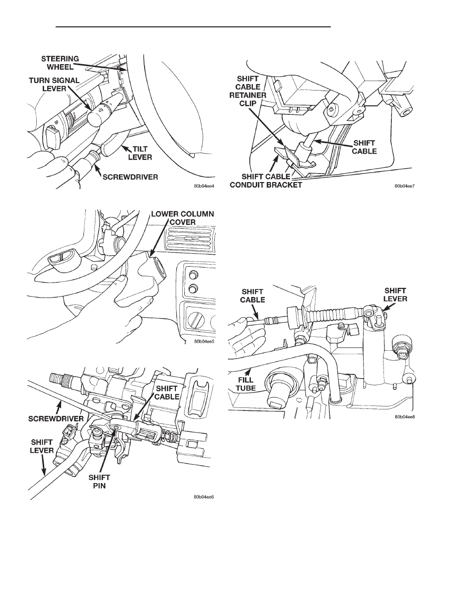
CAUTION: Column must be tilted fully upward to
remove cable retainer clip.

(8) From underhood side of dash panel, unseat

grommet and pull cable from interior of vehicle.

(9) Raise vehicle on hoist and unbolt fill tube

bracket. Rotate fill tube to gain access to shift cable
clamp.

(10) Loosen shift cable clamp on transaxle.
(11) Disconnect

shifter

cable

from

shift

lever

assembly at transaxle (Fig. 19).

(12) Remove cable from underneath vehicle.

INSTALLATION

(1) Route new cable from underside of vehicle. The

cable must be routed between the engine block and
the heater return tube (Fig. 20).

(2) Snap new transaxle cable on to transaxle shift

lever assembly.

(3) Set shift lever assembly in park position at

transaxle. This is the most rearward position. Verify
park sprag is fully engaged.

Fig. 15 Tilt Lever Screw Removal

Fig. 16 Lower Column Cover Removal

Fig. 17 Cable Removal From Shift Pin

Fig. 18 Shift Cable Retainer Clip Removal

Fig. 19 Cable Removal

300M

TRANSAXLE

21 - 17

REMOVAL AND INSTALLATION (Continued)

CAUTION: Park

sprag

must

be

engaged

when

adjusting linkage. Rock vehicle back and forth to
ensure that park sprag is fully engaged.

(4) Tighten shift cable clamp bolt.
(5) Rotate fill tube to original location. Install and

tighten fill tube bracket bolt.

(6) Route transaxle shift cable through hole in

dash panel.

(7) Install cable grommet in dash panel.
(8) Route transaxle shift cable along steering col-

umn (Fig. 21).

(9) Connect transaxle shift cable to shift cable con-

duit bracket and secure with new clip.

(10) Attach shift cable (with shift lever in park

position) to attaching stud (pin) by snapping into
place.

(11) Shift the transaxle lever to park. Move the

steering column to full tilt downward. Put the col-
umn shifter in park with key removed.

(12) Adjust cable by rotating the adjuster into lock

position (Fig. 22). The adjuster will click when lock is
fully adjusted.

(13) Reinstall upper and lower steering column

shrouds. Then install underpanel silencer/duct.

(14) Check shifter for proper operation. It should

operate smoothly without binding. The engine starter
should crank in Park or Neutral positions only.

GEARSHIFT CABLE–FLOOR SHIFT

REMOVAL

(1) Remove shift handle (Fig. 23).

(2) Remove console bezel from vehicle.
(3) Loosen nut on shift cable adjust lever (Fig. 24).
(4) Remove retaining clip from shift cable conduit

bracket.

(5) Disconnect shifter cable from cable attach stud

(pin).

(6) Remove cable from center console routing.

Leave flat on floor for ease of removal.

(7) From underhood side of dash panel unseat

grommet and remove cable from interior of vehicle.

Fig. 20 Shift Cable Routing

Fig. 21 Shift Cable Routing

Fig. 22 Shift Cable Adjuster Lock

Fig. 23 Shift Handle Retaining Screw

21 - 18

TRANSAXLE

300M

REMOVAL AND INSTALLATION (Continued)

(8) Raise vehicle on hoist and disconnect fill tube

bracket from transaxle. Rotate fill tube to gain access
to shift cable clamp.

(9) Loosen bolt that clamps shift cable to tran-

saxle.

(10) Disconnect

shifter

cable

from

shift

lever

assembly at transaxle.

(11) Remove cable from underneath vehicle.

INSTALLATION

(1) Reroute new cable from underside of vehicle.

The cable must be routed between the engine block
and the heater return tube (Fig. 25).

(2) Snap new transaxle cable on to shift lever

assembly.

(3) Set shift lever assembly in park position at

transaxle. This is the most rearward position. Verify
park sprag is fully engaged.

CAUTION: Park

sprag

must

be

engaged

when

adjusting linkage. Rock vehicle back and forth to
ensure that park sprag is fully engaged.

(4) Tighten shift cable clamp bolt.
(5) Rotate fill tube to original location. Install and

tighten fill tube bracket bolt.

(6) Route transaxle shift cable through hole in

dash panel.

(7) Install cable grommet in dash panel.
(8) Route transaxle shift cable under A/C duct,

over central distribution duct, through support strut
and air bag mounting bracket. Then route over car-
peting and down to the shifter bracket (Fig. 26).

(9) Place shifter in the Park position.
(10) Route cable through hole in shifter bracket

and attach to cable attaching stud (pin) by snapping
into place.

(11) Install a new clip onto the cable at the shifter

bracket.

(12) Tighten the adjuster nut.
(13) Reinstall console bezel and shifter handle.

Firmly press the shifter handle downward and
tighten the fastener.

(14) Check shifter for proper operation. It should

operate smoothly without binding. The vehicle should
crank in Park or Neutral only.

FLOOR SHIFTER

REMOVAL

(1) Remove shifter handle and console bezel.
(2) Loosen adjuster nut on shifter adjuster.
(3) Loosen locking clip on interlock cable.
(4) Disconnect shifter cable from cable attaching

stud (pin).

(5) Disconnect interlock cable from shifter base

slot. Be careful not to break tab on interlock cable
conduit end fitting.

(6) Remove the five floor pan attaching nuts from

the shifter base and shift cable bracket.

(7) Remove shifter assembly from vehicle.

Fig. 24 Shift Cable Adjust Lever Nut

Fig. 25 Shift Cable Routing

Fig. 26 Interior Cable Routing

300M

TRANSAXLE

21 - 19

REMOVAL AND INSTALLATION (Continued)

INSTALLATION

(1) Install new shifter. Make sure eyelet of shifter

cable is inside of shifter housing.

(2) Install five floor pan attaching nuts to hold

shifter base and shift cable bracket.

(3) Place shift lever and transaxle in park. Verify

park sprag is fully engaged.

CAUTION: Park

sprag

must

be

engaged

when

adjusting linkage. Rock vehicle back and forth to
ensure that park sprag is fully engaged.

(4) With the ignition in the lock position, attach

shift cable eyelet to cable attaching stud (pin).

(5) Slip interlock cable core wire into interlock

adjustment lever groove. Make sure the interlock
cable slug is seated in the groove.

(6) Slip interlock cable conduit end fitting into

base and snap into place.

CAUTION: Both the shift cable and the interlock
cable must be adjusted. Refer to the cable adjust-
ment procedures in this manual.

AUTOSTICK SHIFTER

The autostick shifter has the same service proce-

dures as the standard floor shifter. Refer to the appli-
cable floor shifter section for service procedures.

The autostick shifter incorporates a switch that

interacts with the transmission control module. Refer
to the Diagnosis and Testing section for diagnostic
procedures.

The switch is serviceable only as part of the floor

shifter assembly. Therefore the shifter should be
replaced, and adjustments made to the cables, if
switch replacement is necessary.

COLUMN SHIFT INTERLOCK SERVICE

The interlock cassette slides into the housing

behind the lock cylinder (Fig. 27). The cable at the
rear of the cassette attaches to a locking arm on the
shifter mechanism. The column shift interlock
system is only adjusted after installing a new
cassette. It can’t be adjusted more than once. If
the system operates incorrectly, install and
adjust a new interlock cassette.

REMOVAL

(1) Depress the tab on the top of the cassette.
(2) Slide the interlock cassette out of the housing.
(3) Remove the cable from the locking arm on the

shifter mechanism.

INSTALLATION

(1) Ensure the latch rotates freely on the shifter

gate (Fig. 28).

(2) With the shifter in Park and the key removed,

install the cable over the hook on locking arm of the
shifter mechanism.

(3) Slide the cassette into the housing until it locks

in place.

(4) To adjust the interlock system, push the adjust-

ment tab in until it stops (Fig. 29). The adjustment
tab will click as it moves into position. Ensure the
tab is fully depressed.

FLOOR SHIFT INTERLOCK SERVICE

The interlock cable slides into the housing behind

the lock cylinder and attaches to the floor mounted
shifter. The floor shift interlock system is adjusted by
an integral locking clip in the interlock assembly. If
the system requires adjustment and not replacement,
refer to the Floor Shift Interlock Adjustment proce-
dure in this section.

REMOVAL

(1) Remove shifter handle.
(2) Remove the bezel from the shifter console.

Fig. 27 Ignition Interlock Cassette–Column Shift

Fig. 28 Latch and Shifter Gate

21 - 20

TRANSAXLE

300M

REMOVAL AND INSTALLATION (Continued)


Content   ..  284  285  286  287   ..