Chrysler 300M, Dodge Interpid. Manual - part 305


  Index      Chrysler     Chrysler 300M / Concorde / Interpid / LHS, Dodge Interpid - service repair manual 2000-2004 year


Search            


Content   ..  303  304  305  306   ..


Chrysler 300M, Dodge Interpid. Manual - part 305


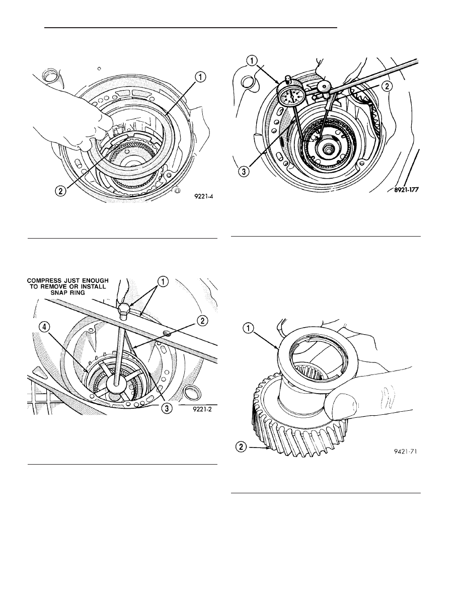
(32) Install 2/4 clutch retainer (Fig. 120).

(33) Set up Tool 5058 as shown in (Fig. 121). Com-

press 2/4 clutch just enough to facilitate snap ring
installation.

(34) Measure 2/4 clutch clearance: Set up dial

indicator as shown in (Fig. 122). Press down clutch
pack with finger and zero dial indicator. Record mea-
surement in four (4) places and take average reading.
The 2/4 clutch pack clearance is 0.76 to 2.64 mm
(0.030 to 0.104 inch). 
If not within specifications,
the clutch is not assembled properly. There is no
adjustment for the 2/4 clutch clearance.

(35) Install the #7 needle bearing to the rear sun

gear (Fig. 123). The number 7 needle bearing has
three antireversal tabs and is common with the
number 5 and number 2 position. The orienta-
tion should allow the bearing to seat flat
against the rear sun gear. A small amount of
petrolatum can be used to hold the bearing to
the rear sun gear.

Fig. 120 Install 2/4 Clutch Retainer

1 - 24 CLUTCH RETAINER
2 - 24 CLUTCH RETURN SPRING

Fig. 121 Install 2/4 Clutch Retainer Snap Ring

1 - TOOL 5058
2 - SCREWDRIVER
3 - SNAP RING
4 - 24 CLUTCH RETAINER

Fig. 122 Check 2/4 Clutch Clearance

1 - DIAL INDICATOR
2 - HOOK TOOL
3 - DIAL INDICATOR TIP TOOL 6268

Fig. 123 Number 7 Bearing

1 - #7 BEARING
2 - REAR SUN GEAR

LH

TRANSAXLE

21 - 39

42LE AUTOMATIC TRANSAXLE (Continued)

(36) Install rear sun gear and #7 needle bearing

(Fig. 124).

(37) Install front carrier/rear annulus assembly

and #6 needle bearing (Fig. 125).

(38) Install front sun gear assembly and #4 thrust

washer (Fig. 126).

(39) Determine proper #4 thrust plate thick-

ness.

(a) Select the thinnest #4 thrust plate thickness.
(b) Install #4 thrust plate (Fig. 127) using petro-

latum to hold into position.

Fig. 124 Install Rear Sun Gear

1 - #7 NEEDLE BEARING
2 - REAR SUN GEAR

Fig. 125 Install Front Carrier/Rear Annulus Assy.

1 - #6 NEEDLE BEARING
2 - FRONT CARRIER AND REAR ANNULUS ASSEMBLY (TWIST
AND PULL OR PUSH TO REMOVE OR INSTALL).

Fig. 126 Install Front Sun Gear Assembly

1 - FRONT SUN GEAR ASSEMBLY
2 - #4 THRUST WASHER (FOUR TABS)

Fig. 127 No. 4 Thrust Plate

1 - OVERDRIVE SHAFT ASSEMBLY
2 - #4 THRUST PLATE (SELECT)
3 - PETROLATUM (FOR RETENTION)

21 - 40

TRANSAXLE

LH

42LE AUTOMATIC TRANSAXLE (Continued)

(c) Install input clutch assembly. Ensure the

input clutch assembly is completely seated by view-
ing position through input speed sensor hole (Fig.
128). If view through input speed sensor hole
is not as shown in (Fig. 128), the input
clutches assembly is not seated properly.

(d) Remove the oil pump o-ring (Fig. 129) and

install oil pump and gasket to transaxle. Use
screw-in dowels or phillips-head screwdrivers
to align pump to case. Be sure to reinstall
O-ring on oil pump after selecting the proper
No. 4 thrust plate.

(e) Measure the input shaft end play with the

transaxle in the vertical position. This will ensure
that the measurement will be accurate.

(f) Set up and measure endplay using End Play

Set 8266 and Dial Indicator Set C3339 as shown in
(Fig. 130).

(g) Measure input shaft end play. Input shaft

end play must be .005 to .025 inch. For exam-
ple, if end play reading is 0.055 inch, select No. 4
Thrust Plate which is 0.071 to 0.074 thick. This
should provide an input shaft end play reading of
0.020 inch, which is within specifications.

(h) See chart to select the proper No. 4 thrust plate.

NO. 4 THRUST PLATE CHART

PART NUMBER

THICKNESS

3836237AB

1.73mm (0.068 in.)

4431666AB

1.80mm (0.071 in.)

3836238AB

1.96mm (0.077 in.)

4431667AB

2.03mm (0.080 in.)

3836239AB

2.16mm (0.085 in.)

4431668AB

2.24mm (0.088 in.)

3836240AB

2.39mm (0.094 in.)

4431669AB

2.46mm (0.097 in.)

3836241AB

2.62mm (0.103 in.)

4446670AB

2.67mm (0.105 in.)

4446671AB

2.90mm (0.114 in.)

(i) Remove oil pump, gasket, and input clutch

assembly to gain access to and install proper #4
thrust plate.

CAUTION: If view through input speed sensor hole
is not as shown in (Fig. 128), the input clutches
assembly is not seated properly.

Fig. 128 View Through Turbine Speed Sensor Hole

1 - TRANSAXLE COOLER LINE
2 - TURBINE SPEED SENSOR HOLE

Fig. 129 Remove Oil Pump O-Ring

1 - OIL PUMP ASSEMBLY
2 - O-RING

Fig. 130 Measure Input Shaft End Play Using Tool

8266—Typical

1 - TOOL 8266–8
2 - TOOL 8266–2
3 - TOOL C-3339

LH

TRANSAXLE

21 - 41

42LE AUTOMATIC TRANSAXLE (Continued)

(40) Install input clutch assembly with proper

thrust plate (Fig. 131).

(41) Install #1 caged needle bearing (Fig. 132).

(42) Replace cooler by-pass valve if transmission

failure has occurred (Fig. 133).

CAUTION: By-pass valve must be replaced if trans-
mission failure occurs.

NOTE: To align oil pump, gasket, and case during
installation, use threaded dowels or phillips screw-
drivers.

(43) Install oil pump gasket (Fig. 134).

Fig. 131 Install Input Clutch Assembly

1 - INPUT CLUTCH ASSEMBLY

Fig. 132 Install Caged Needle Bearing

1 - #1 CAGED NEEDLE BEARING
2 - NOTE: TANGED SIDE OUT

Fig. 133 Install By-Pass Valve

1 - BYPASS VALVE

Fig. 134 Install Oil Pump Gasket

1 - BELL HOUSING
2 - OIL PUMP GASKET

21 - 42

TRANSAXLE

LH

42LE AUTOMATIC TRANSAXLE (Continued)


Content   ..  303  304  305  306   ..