Chrysler 300M, Dodge Interpid. Manual - part 63
OPERATION
The primary functions of the controller antilock
brake (CAB) are to:
• Monitor the antilock brake system for proper
operation.
• Detect wheel locking or wheel slipping tenden-
cies by monitoring the speed of all four wheels of the
vehicle.
• Control fluid modulation to the wheel brakes
while the system is in an ABS mode.
• Store diagnostic information.
• Provide communication to the DRBIIIt scan tool
while in diagnostic mode.
• Illuminate the ABS and BRAKE (with loss of
EVBP) warning indicator lamps.
• (With traction control only) Illuminate the TRAC
ON lamp in the message center on the instrument
panel when a traction control event occurs.
• (with traction control only) Illuminate the TRAC
OFF lamp when the amber ABS warning indicator
lamp illuminates.
The CAB constantly monitors the antilock brake
system for proper operation. If the CAB detects a
fault, it will turn on the amber ABS warning indica-
tor lamp and disable the antilock braking system.
The normal base braking system will remain opera-
tional.
NOTE: If the vehicle is equipped with traction con-
trol, the TRAC OFF lamp will illuminate anytime the
amber ABS warning indicator lamp illuminates.
The CAB continuously monitors the speed of each
wheel through the signals generated by the wheel
speed sensors to determine if any wheel is beginning
to lock. When a wheel locking tendency is detected,
the CAB commands the CAB command coils to actu-
ate. The coils then open and close the valves in the
HCU that modulate brake fluid pressure in some or
all of the hydraulic circuits. The CAB continues to
control pressure in individual hydraulic circuits until
a locking tendency is no longer present.
The CAB contains a self-diagnostic program that
monitors the antilock brake system for system faults.
When a fault is detected, the amber ABS warning
indicator lamp is turned on and the fault diagnostic
trouble code (DTC) is then stored in a diagnostic pro-
gram memory. These DTC’s will remain in the CAB
memory even after the ignition has been turned off.
The DTC’s can be read and cleared from the CAB
memory by a technician using the DRBIII
t scan tool.
If not cleared with a DRBIII
t scan tool, the DTC will
be automatically cleared from the CAB memory after
the identical fault has not been seen during the next
3,500 miles.
CAB INPUTS
• Wheel speed sensors (four)
• Brake lamp switch
• Ignition switch
• System and pump voltage
• Ground
• Traction control OFF switch (via BUS) (if
equipped)
• Diagnostic communication (PCI)
CAB OUTPUTS
• Amber ABS warning indicator lamp actuation
(via BUS)
• Instrument cluster (MIC) communication (PCI)
• Traction control lamps (if equipped)
• Diagnostic communication (PCI, via BUS)
REMOVAL
To remove the CAB, the ICU must be removed
from the vehicle and disassembled. (Refer to 5 -
BRAKES
-
ABS/HYDRAULIC/MECHANICAL/ICU
(INTEGRATED CONTROL UNIT) - REMOVAL)
INSTALLATION
To install the CAB, it must be attached to the
HCU, forming the ICU. (Refer to 5 - BRAKES - ABS/
HYDRAULIC/MECHANICAL/ICU
(INTEGRATED
CONTROL UNIT) - ASSEMBLY)
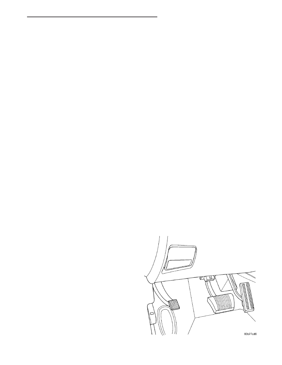
DATA LINK CONNECTOR
DESCRIPTION
The data link connector is located inside the vehi-
cle, below instrument panel next to the center col-
umn (Fig. 2).
Fig. 2 DATA LINK CONNECTOR
LH
ELECTRONIC CONTROL MODULES
8E - 5
CONTROLLER ANTILOCK BRAKE (Continued)