Content .. 1788 1789 1790 1791 ..
Chrysler 300/300 Touring/300C, Dodge Magnum. Manual - part 1790
Injector opens (start of injection)
The solenoid valve is energized with the pickup current which serves to ensure that it open quickly. The force
exerted by the triggered solenoid now exceeds that of the valve spring and the armature opens the bleed orifice.
Almost immediately, the high-level pick-up current is reduced to the lower holding current required for the electro-
magnet. This is possible due to the magnetic circuit’s air gap now being smaller. When the bleed orifice opens, fuel
can flow from the valve control chamber into the cavity situated above it, and from there via the fuel return to the
tank. The bleed orifice prevents complete pressure balance, and the pressure in the valve control chamber sinks as
a result. This leads to the pressure in the valve-control chamber being lower than that in the nozzle’s chamber
volume which is still at the same pressure level as the rail. The reduced pressure in the valve-control chamber
causes a reduction in the force exerted on the control plunger, the nozzle needle open as a result, and injection
starts.
Injector opens fully
The control plunger reaches its upper stop where it remains supported by a cushion of fuel which is generated by
the flow of fuel between the bleed and feed orifices. The injector nozzle has now opened fully, and the fuel is
injected into the combustion chamber at a pressure almost equal to that in the fuel rail.
Injector closes (end of injection)
As soon as the solenoid valve is no longer triggered, the valve spring forces the armature downwards and the ball
closes the bleed orifice. The armature is a 2–piece design. Here, although the armature plate is guided by a driver
shoulder in its downward movement, it can “overspring” with the return spring so that it exerts no downwards-acting
forces on the armature and the ball. The closing of the bleed orifice lead to pressure build up in the control chamber
via the input from the feed orifice. This pressure is the same as that in the rail and exerts an increased force on the
control plunger through its end face. This force, together with that of the spring, now exceeds the force exerted by
the chamber volume and the nozzle needle closes. Injection ceases as soon as the nozzle needle comes up against
its bottom stop again .
STANDARD PROCEDURE
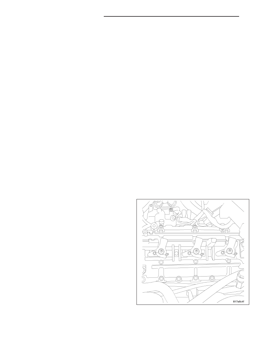
CLEANING FUEL INJECTORS
NOTE: Before cleaning the injector recesses, seal
the injector holes in the injector recesses with the
appropriate pin to prevent debris from falling into
the recesses and entering the motor.
1. Using a lint-free rag, wipe the cylinder head around
the fuel injector.
2. Wipe out injector recesses with a lint-free cloth,
then clean with a cylinder brush.
3. Clean the bottom of the cylinder recess with a
round brush.
4. Blow out the recess and clean again with a lint-free
cloth and cover over.
5. Perform these steps for each injector recess.
NOTE: DO NOT clean the tip of the injector with a
wire brush. Use a lint—free cloth.
6. Clean injector body with a wire brush.
7. Clean injector tips with a lint-free cloth.
NOTE: Do Not apply antiseize lubricant to the injector nozzle, apply only to the injector body.
8. Grease injector body with antiseize lubricant.
14 - 234
FUEL INJECTION - DIESEL
LX