Chrysler 300/300 Touring/300C, Dodge Magnum. Manual - part 167


  Index      Chrysler     Chrysler 300/300 Touring/300C, Dodge Magnum - service repair manual


Search            


Content   ..  165  166  167  168   ..


Chrysler 300/300 Touring/300C, Dodge Magnum. Manual - part 167


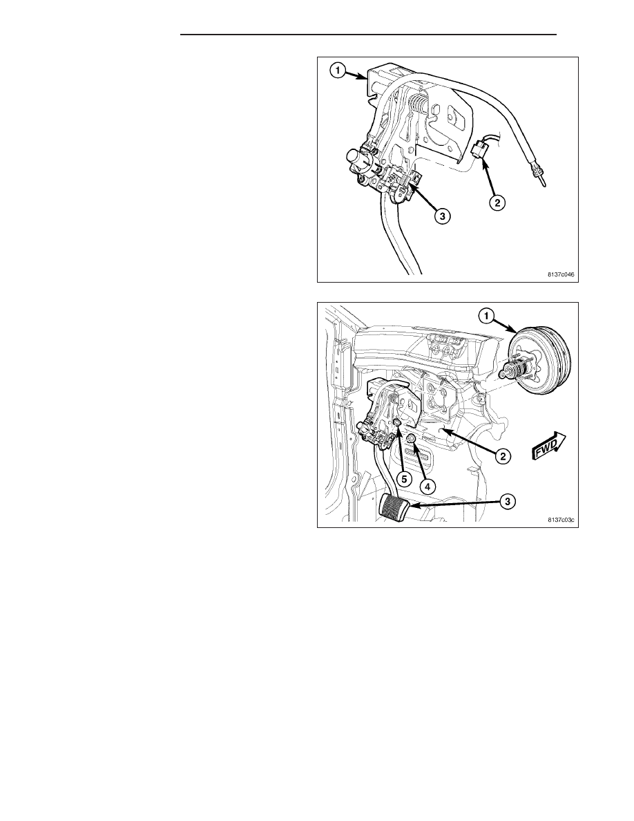
7. Disconnect wiring connector (2) at brake pedal

position sensor (3).

8. Remove four power brake booster mounting nuts

(4).

9. Remove two nuts (5) fastening pedal bracket to

upper dash panel (2).

10. Push power brake booster (1) forward into engine

compartment as far as possible by hand. Do not
force it.

11. Remove adjustable brake pedal assembly (3).

12. Remove adjuster cable at brake pedal gear drive.

INSTALLATION

1. Attach cable to brake pedal gear drive.

5 - 110

BRAKES - BASE

LX

2. Install adjustable brake pedal assembly (3) under

instrument panel and slide over booster push rod.

3. From engine compartment side, push power brake

booster (1) mounting studs back through dash
panel (2) and brake pedal bracket.

4. Install two nuts (5) fastening pedal bracket to upper

dash panel (2). Do not tighten at this time.

5. Install four power brake booster mounting nuts (4).

Tighten nuts to 25 N·m (18 ft. lbs.) torque.

6. Tighten two upper mounting nuts (5) to 25 N·m (18

ft. lbs.) torque.

7. Connect wiring connector (2) at brake pedal posi-

tion sensor (3).

8. Slide booster push rod (5) onto brake pedal pin (4).

Install NEW retaining clip (3) securing push rod to
brake pedal.

9. Install and adjust brake lamp switch (2). (Refer to 8

- ELECTRICAL/LAMPS/LIGHTING - EXTERIOR/
BRAKE LAMP SWITCH - INSTALLATION)

LX

BRAKES - BASE

5 - 111

10. Connect battery negative cable (2) to battery post.

It is important that this is performed properly.
(Refer to 8 - ELECTRICAL/BATTERY SYSTEM -
STANDARD PROCEDURE)

11. Synchronize brake pedal to accelerator pedal,

then connect adjuster cable (1) to adjuster motor
(2). (Refer to 5 - BRAKES/HYDRAULIC/MECHAN-
ICAL/PEDAL - STANDARD PROCEDURE)

12. If vehicle is equipped with memory seats, the sys-

tem will need to be initialized. Refer to appropriate
diagnostic information.

13. Test operation of adjustable pedals.

14. Road test vehicle testing operation of brakes and

accelerator.

5 - 112

BRAKES - BASE

LX

BOOSTER - POWER BRAKE

REMOVAL

BOOSTER

1. Move driver’s seat to full rearward position.

2. Disconnect and isolate battery negative cable (2)

from battery post.

3. Remove windshield wiper module. (Refer to 8 -

ELECTRICAL/WIPERS/WASHERS/WIPER

MOD-

ULE - REMOVAL)

4. Remove master cylinder. (Refer to 5 - BRAKES/

HYDRAULIC/MECHANICAL/MASTER CYLINDER -
REMOVAL)

5. If equipped with MK25 and Electronic Stability Pro-

gram (ESP), disconnect wiring harness (6) connec-
tor at pedal travel sensor (7) on power brake
booster (3).

6. If equipped with MK25 and ESP, disconnect wiring

harness (6) connector at active brake booster sole-
noid (4).

LX

BRAKES - BASE

5 - 113


Content   ..  165  166  167  168   ..