Chrysler Town & Country/Voyager, Dodge Caravan, Plymouth Voyager. Manual - part 309


  Index      Chrysler     Chrysler Town & Country/Voyager, Dodge Caravan, Plymouth Voyager - service repair manual 1992 year


Search            


Content   ..  307  308  309  310   ..


Chrysler Town & Country/Voyager, Dodge Caravan, Plymouth Voyager. Manual - part 309


PISTON RINGS—INSTALLATION

(1) The No. 1 and No. 2 piston rings have a different

cross section. Install rings with manufacturers mark
and size mark facing up, to the top of the piston (Fig.
10).

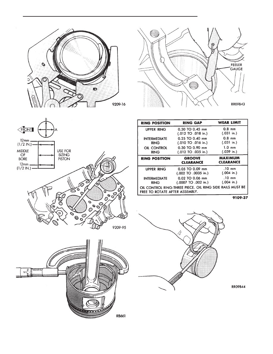
Fig. 4 Remove Piston Rings

Fig. 5 Checking Cylinder Bore Size

Fig. 6 Piston Clearance and Wear

Fig. 7 Check Gap on Piston Rings

Fig. 8 Piston Ring Specification Chart

Fig. 9 Piston Ring Clearance

.

3.0L ENGINE

9 - 67

CAUTION: Install piston rings in the following order:

(a) Oil ring expander.
(b) Upper oil ring side rail.
(c) Lower oil ring side rail.
(d) No. 2 Intermediate piston ring.
(e) No. 1 Upper piston ring.

(2) Install the side rail by placing one end between

the piston ring groove and the expander. Hold end
firmly and press down the portion to be installed until
side rail is in position. Do Not use a piston ring
expander 
(Fig. 11).

(3) Install upper side rail first and then the lower

side rail.

(4) Install No. 2 piston ring and then No. 1 piston

ring (Fig. 12).

(5) Position piston ring end gaps as shown in (Fig.

13).

(6) Position oil ring expander gap at least 45° from

the side rail gaps but not on the piston pin center or on
the thrust direction.

(7) Connecting rod front mark 72 must always face

forward, toward timing belt end. (Fig. 14)

(8) Install the piston and connecting rod assembly

into there respective bore from the cylinder block top.

CAUTION: Piston assemblies are not to be inter-
changed from bank to bank.

(9) Check alignment marks made during disassem-

bly and that bearing position notches new or used are
on the same side as shown in (Fig. 15).

CONNECTING ROD CLEARANCE

(1) Following procedures specified in the Standard

Service Procedures Section for Measuring Main Bear-
ing Clearance and Connecting Rod Bearing Clearance.
(Fig. 16). Refer to (Fig. 18) for specifications.

(2) Tighten nuts to 52 N

Im (38 ft. lbs.).

(3) Remove connecting rod cap and measure Plasti-

gage (Fig. 16).

Fig. 10 Piston Ring Installation

Fig. 11 Installing Side Rail

Fig. 12 Installing Upper and Intermediate Rings

Fig. 13 Piston Ring End Gap Position

9 - 68

3.0L ENGINE

.

CAUTION: Do not rotate crankshaft or the Plastigage
may be smeared.

CONNECTING ROD SIDE CLEARANCE

Using a feeler gauge, check connecting rod side

clearance (Fig. 17). Refer to (Fig. 18) for specification.

Fig. 14 Identify Piston/Rod Assembly

for Cylinder Installation

Fig. 15 Connecting Rod and Cap

Fig. 16 Connecting Rod Checking

Bearing Clearance

Fig. 17 Checking Connecting Rod Side Clearance

Fig. 18 Connecting Rod Clearance Specifications

.

3.0L ENGINE

9 - 69

CRANKSHAFT AND CYLINDER BLOCK,ASSEMBLY
SERVICE

CRANKSHAFT SERVICE

The crankshaft is supported in four main bearings.

All upper bearing shells in the crankcase have oil
grooves. All lower bearing shells in stalled in the
monoblock main bearing cap are plain. Crankshaft end
play is controlled by thrust washers on the number
three main bearing journal.

CRANKSHAFT—REMOVAL

(1) Remove front mounted oil pump assembly and

gasket (Figs. 1 and 2).

(2) Remove rear oil seal retainer and seal as assem-

bly (Fig. 3).

(3) Release monoblock main bearing cap bolts

evenly. Remove lower bearing shells and identify for
reassembly.

(4) Lift out crankshaft and remove upper thrust

washers from each side of number three main bearing
in the crankcase (Fig. 1).

INSPECTION

Visually check the main and connecting rod bearing

journals for wear, scuffs or scoring and replace if
necessary.

CRANKSHAFT OIL CLEARANCE

MECHANICAL MEASUREMENT

Measure the journal outside diameter and the main

bearing inside diameter (Figs. 4 and 5). If the clearance
exceeds the specifications limit (Fig. 6). Replace the
main bearing(s) and if necessary replace the crank-
shaft.

Fig. 1 Crankshaft and Cylinder Block

Fig. 2 Oil Pump Assembly

9 - 70

3.0L ENGINE

.


Content   ..  307  308  309  310   ..