Chrysler Town & Country/Voyager, Dodge Caravan, Plymouth Voyager. Manual - part 197


  Index      Chrysler     Chrysler Town & Country/Voyager, Dodge Caravan, Plymouth Voyager - service repair manual 1992 year


Search            


Content   ..  195  196  197  198   ..


Chrysler Town & Country/Voyager, Dodge Caravan, Plymouth Voyager. Manual - part 197


VARIANCE PROCEDURE

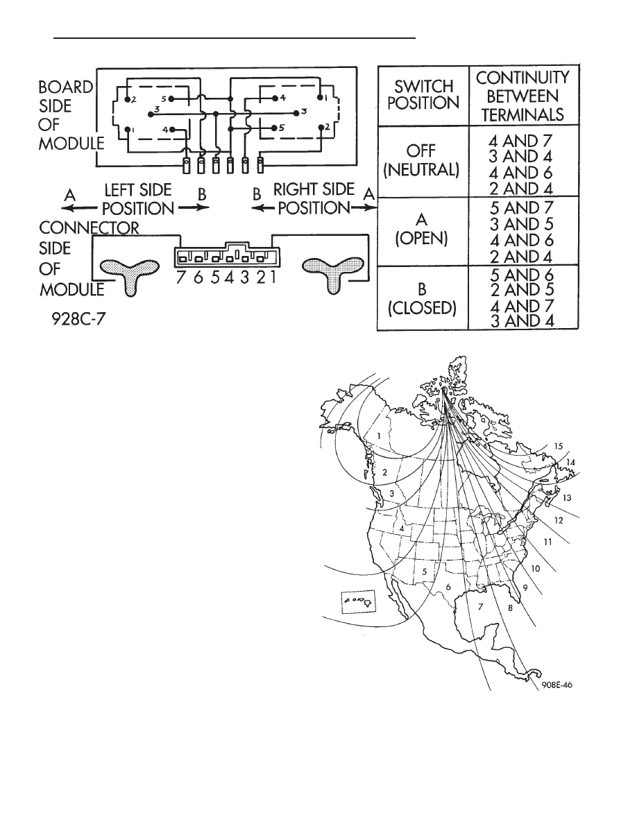
Variance is the difference between magnetic North

and geographic North refer to Fig. 4 for variance
number. To adjust the compass variance set the CMTC
to Compass/Temperature mode and depress both the
US/M and STEP buttons for 5 seconds. The word VAR
and the last variance zone will be displayed. Depress
the US/M button to select the desired zone. Depress the
STEP button to set the new variance zone and resume
normal operation. If both buttons are held for 10
seconds instead of 5 seconds the CMTC will set vari-
ance to 8 and enter the fast calibration mode.

TRAVELER MESSAGES

Traveler data is obtained from the Body Controller

on the CCD lines. If the brightness level is improper or
the data displayed is wrong then check CCD commu-
nication by the following test. STEP the CMTC to the
elapsed time ET mode and simultaneously press both
the US/M and STEP buttons to reset the module. If the
elapsed time clock does not reset or fails to up-date
then check the CCD lines and Body Controller. Run self
diagnostics before replacing CMTC. The DRB II is
recommended for checking out the CCD lines and Body
Controller.

DEMAGNETIZING PROCEDURE

Every vehicle has its own magnetic field. This mag-

netic field is created by the various processes a steel
roof goes through when the vehicle is built. A magnetic
field can also be created if the roof is subjected to a
magnet. Example:
• Magnetic C.B. antenna

• Magnetic tipped screwdriver

• etc.

If the roof becomes magnetized use a demagnetizer

tool 6029 to demagnetize the roof.

Fig. 3 Power Vent Window Continuity Test

Fig. 4 Variance Settings

.

OVERHEAD CONSOLE

8C - 3

In this demagnetizing procedure you will use the

demagnetizing tool to demagnetize the roof and mount-
ing screws in the overhead console. It is important that
you follow the instructions below exactly. The mount-
ing screws and the mounting brackets around the
compass area are steel, and therefore aid in the demag-
netizing of the roof panel.

(1) Be sure the ignition switch is in the OFF position

before you begin the demagnetize procedure.

(2) Plug the demagnetizing tool into a standard

110/115 volt AC outlet, keeping the demagnetizing tool
at least 12 inches away from the compass area when
plugging it in.

(3) Slowly approach and contact the console mount-

ing screw with the plastic coated tip of the tool for at
least two seconds.

(4) With the demagnetizing tool still energized,

slowly back it away from the screw until the tip is at
least 12 inches from the screw head.

(5) After you have pulled at least 12 inches from the

last screw, remove the demagnetizing tool from inside
vehicle and disconnect it from the electrical outlet.

(6) Place an 8-1/2 X 11 inch piece of paper lengthwise

on the roof of vehicle directly above compass. The
purpose of the paper is to protect the roof panel from
scratches and define the area to be demagnetized.

(7) Plug in the demagnetizing tool, keeping it at

least two feet away from the compass unit.

(8) Slowly approach the center of the roof panel at

the windshield with the demagnetizing tool plugged in.

(9) Contact the roof panel with the tip of the tool.

Using slow sweeping motions of 1/2 inch between
sweeps. Move the tool approximately four inches either
side of the centerline and at least 11 inch back from the
windshield.

(10) With the demagnetizing tool still energized,

slowly back away from the roof panel until the tip is at
least two feet from the roof before unplugging the tool.

(11) Recalibrate compass.

SELF-DIAGNOSTIC TEST

(1) The ignition switch in the OFF position, press

both the STEP button and the US/M button.

(2) Turn ignition switch ON.
(3) Display showing do, release buttons:

• STEP button advances test to next procedure

• US/M button repeats last procedure

(4) Pressing US/M button while do is displayed

causes CMTC to exit diagnostics and display current
heading as a number between 0 and 359 in tempera-
ture of the display.

(5) Pressing STEP button, symbols and numbers

corresponding to North/South and East/West calibra-
tion are displayed.

(6) With d1 displayed, press STEP button to show

the internal diagnostics:

(a) F1: Internal failure - replace module.
(b) F2: CCD bus failure:

• Check wiring

• Check any other body computer CCD function, if
CCD functions are OK, and wiring is OK, then replace
module

(7) With d2 displayed, press STEP button and test

all segment. If any segment fails to light, replace
module.

(8) With d3 displayed, press STEP button and EXIT

diagnostics and resume normal operation.

OVERHEAD CONSOLE REPLACEMENT

(1) Unscrew the mounting screws (Fig. 5).

(2) Slide console forward toward windshield until

the console unhooks from roof bracket.

(3) Disconnect wire harness from console.
(4) For installation reverse above procedures.

COMPASS MODULE REPLACEMENT

(1) Remove overhead console and disconnect wiring.
(2) Remove two forward screws and pry rear of

compass module along the sides from the console
housing so 1 of the 2 compass pins clear the console.
Rotate module out of the console.

(3) For installation reverse above procedures.

FRONT HEADER READING LAMP

The front header reading lamps are turned ON and

OFF by pressing on their individual lens cover indents.

FRONT HEADER READING LAMP
REPLACEMENT/LAMP REPLACEMENT

(1) Pull the lamp assembly down, along the sides

from the bracket. Four metal clips hold the lamp in the
bracket (Fig. 6).

Fig. 5 Overhead Console Mounting

8C - 4

OVERHEAD CONSOLE

.

(2) Disconnect the wire harness connector from the

lamp assembly.

(3) After the lamp assembly is free of the vehicle,

pull the metal center reflector to gain access to the
lamp.

(4) For installation reverse above procedures.

Fig. 6 Header Reading Lamp

.

OVERHEAD CONSOLE

8C - 5


Content   ..  195  196  197  198   ..