Chrysler Town & Country/Voyager, Dodge Caravan, Plymouth Voyager. Manual - part 28
CHECK ENGINE LAMP—ENGINE CONTROLLER
OUTPUT
The engine controller supplies a check engine lamp
on/off signal to the instrument panel through the CCD
Bus. The CCD Bus is a communications port. Various
modules use the CCD Bus to exchange information.
The check engine lamp comes on each time the
ignition key is turned ON and stays on for 3 seconds as
a bulb test. The check engine lamp warns the operator
that the engine controller has entered a Limp-in mode.
During Limp-in Mode, the controller attempts to keep
the system operational. The check engine lamp signals
the need for immediate service. In limp-in mode, the
Engine controller compensates for the failure of certain
components that send incorrect signals. The controller
substitutes for the incorrect signals with inputs from
other sensors.
Signals that can trigger the Check Engine
Lamp.
• Coolant Temperature Sensor
• Manifold Absolute Pressure Sensor
• Throttle Position Sensor
• Battery Voltage Input
• An Emission Related System (California vehicles)
• Charging system
The Check Engine Lamp can also be used to display
fault codes. Cycle the ignition switch on, off, on, off, on,
within five seconds and any fault codes stored in the
Engine controller will be displayed. Refer to On Board
Diagnostics in the General Diagnosis—Multi-Point
Fuel Injection, 3.0L Engine section of this Group for
Fault Code Descriptions.
DIAGNOSTIC CONNECTOR—ENGINE CONTROLLER
OUTPUT
The diagnostic connector provides the technician
with the means to connect the DRB II tester to diag-
nosis the vehicle.
ELECTRONIC AUTOMATIC TRANSMISSION
CONTROLLER—ENGINE CONTROLLER OUTPUT
The Electronic Automatic Transmission Controller
and the Engine Controller supply information to each
other through the CCD Bus. The information includes
engine speed and vehicle load. The engine controller
uses the information when adjusting the fuel and
ignition strategy.
EMISSION MAINTENANCE REMINDER (EMR)
LAMP—ENGINE CONTROLLER OUTPUT
The
Emissions
Maintenance
Reminder
System
(EMR) is incorporated into the engine controller. The
engine controller records the vehicle mileage and
stores it into memory every 8 miles. At that time, the
engine controller checks for the 60,000, 82,500, and
120,000 mileage trip points. When the current mileage
matches one of the above mentioned trip points, the
EMR lamp on the instrument panel is activated.
Certain components must be replaced at the indi-
cated mileage, or when the EMR lamp stays on with
the key in the on position, whichever occurs first. After
performing the required maintenance, the EMR lamp
must be reset to turn the lamp off.
For more information, refer to Group 25 or the
appropriate diagnostic manual.
FUEL INJECTORS—ENGINE CONTROLLER OUTPUT
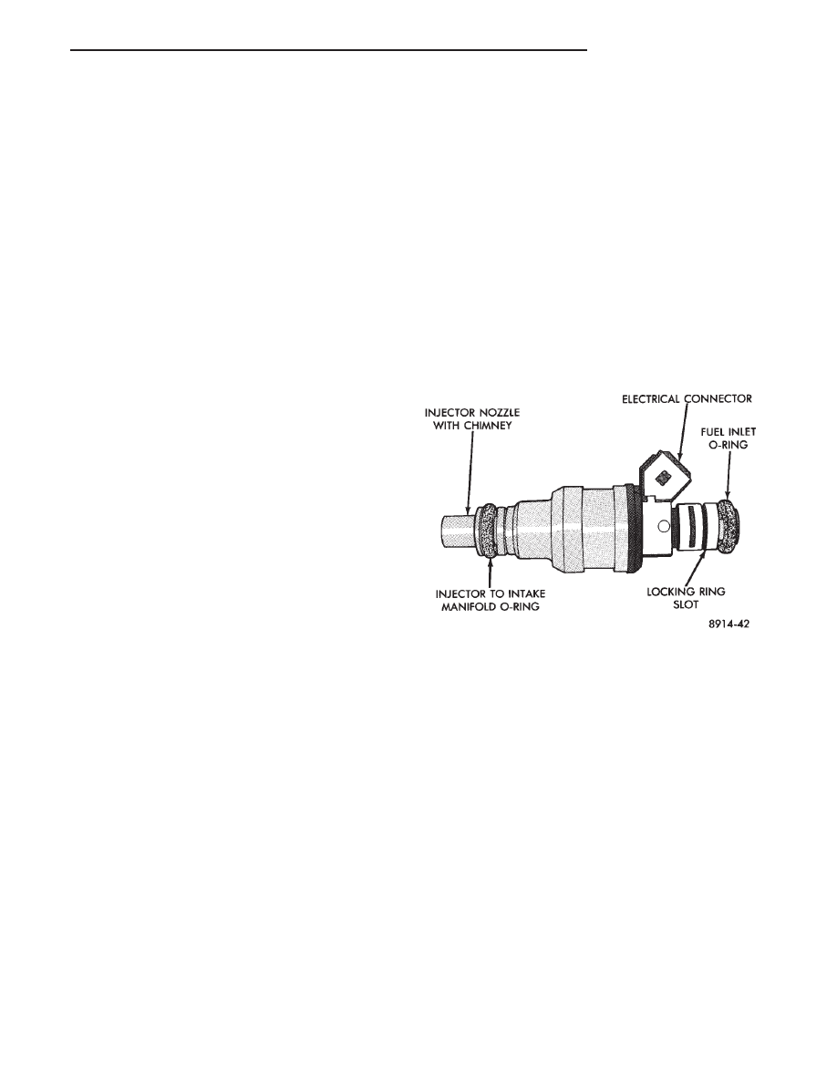
The fuel injectors are electrical solenoids (Fig. 15).
The injector contains a pintle that closes off an orifice
at the nozzle end. When electric current is supplied to
the injector, the armature and pintle move a short
distance against a spring, allowing fuel to flow out the
orifice. Because the fuel is under high pressure, a fine
spray is developed in the shape of a hollow cone. The
spraying action atomizes the fuel, adding it to the air
entering the combustion chamber.
Fig. 15 Fuel Injector—3.0L Engine
.
FUEL SYSTEM
14 - 59