Chrysler Town & Country/Voyager, Dodge Caravan, Plymouth Voyager. Manual - part 14


  Index      Chrysler     Chrysler Town & Country/Voyager, Dodge Caravan, Plymouth Voyager - service repair manual 1992 year


Search            


Content   ..  12  13  14  15   ..


Chrysler Town & Country/Voyager, Dodge Caravan, Plymouth Voyager. Manual - part 14


FUEL DELIVERY SYSTEM

INDEX

page

page

Chassis Fuel Tubes

. . . . . . . . . . . . . . . . . . . . . . . 11

Fuel Filter—All Wheel Drive

. . . . . . . . . . . . . . . . . 11

Fuel Filter—Front Wheel Drive

. . . . . . . . . . . . . . . 10

Fuel Hoses, Clamps, and Quick Connect Fittings

. . 3

Fuel Pump Module Installation—All Wheel Drive

. . 10

Fuel Pump Module Removal—All Wheel Drive

. . . . 9

Fuel Pump Pressure Test—2.5L and 3.0L Engines

5

Fuel Pump Pressure Test—3.3L Engine

. . . . . . . . . 6

Fuel Pump/Level Sending Unit Assembly

Removal—Front Wheel Drive

. . . . . . . . . . . . . . . 8

Fuel Pump/Level Unit Assembly

. . . . . . . . . . . . . . . 5

Fuel Pump/Level Unit Assembly Installation—Front

Wheel Drive

. . . . . . . . . . . . . . . . . . . . . . . . . . . . 9

Fuel System Pressure Release Procedure

. . . . . . . 3

General Information

. . . . . . . . . . . . . . . . . . . . . . . . 3

GENERAL INFORMATION

The front wheel drive van and the all wheel drive van have

different fuel delivery systems. The front wheel drive van
uses a metal fuel tank mounted in the rear of the vehicle. The
all wheel drive van has a plastic fuel tank located on the left
side of the vehicle. The fuel pumps and the chassis fuel tubes
used on front wheel drive vans are different from those used
on all wheel drive vans.

Both the front wheel drive and all wheel drive fuel pump

modules have an internal fuel reservoir, a fuel level sending
unit, and a fuel strainer mounted on the pump housing. Both
systems use quick connect fittings at the fuel tank and
engine. The fuel filter location is the same for both front
wheel drive and all wheel drive vehicles.

FUEL SYSTEM PRESSURE RELEASE PROCEDURE

(1) Loosen fuel filler cap to release fuel tank pres-

sure.

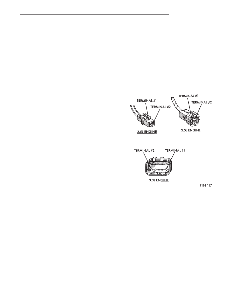
(2) Disconnect injector wiring harness from engine

or main harness.

(3) Connect a jumper wire from terminal Number 1

(ground) of the injector harness (Fig. 1) to engine
ground.

(4) Connect one end of a jumper wire to terminal

Number 2 (positive) of the injector harness (Fig. 1).
Connect the other end to the positive post of the
battery for no longer than 5 seconds. This releases
system pressure.

(5) Remove jumper wires.
(6) Continue fuel system service.

FUEL HOSES, CLAMPS, AND QUICK CONNECT
FITTINGS

HOSES AND CLAMPS

Inspect all hose connections (clamps and quick con-

nect fittings) for completeness and leaks. Replace
cracked, scuffed, or swelled hoses. Replace hoses that
rub against other vehicle components or show sign of
wear.

Fuel injected vehicles use specially constructed

hoses. When replacing hoses, only use hoses marked
EFM/ EFI.

When installing hoses, ensure that they are routed

away from contact with other vehicle components that
could rub against them and cause failure. Avoid contact
with clamps or other components that cause abrasions
or scuffing. Ensure that rubber hoses are properly
routed and avoid heat sources.

The hose clamps have rolled edge to prevent the

clamp from cutting into the hose. Only use clamps that
are original equipment or equivalent. Other types of
clamps may cut into the hoses and cause high pressure
fuel leaks. Tighten hose clamps to 1 N

Im (10 in. lbs.)

torque.

QUICK CONNECT FITTINGS

Some fuel lines have quick connect fittings. The

fittings are designed to speed up the installation and
removal of the fuel lines (Fig. 2).

Quick connect fittings consist of a metal casing, a

Fig. 1 Injector Harness Connectors

.

FUEL SYSTEM

14 - 3

black plastic release ring, a metal locking retainer, and
internal O-rings.

TUBE/FITTING DISASSEMBLY

WARNING: FUEL SYSTEM PRESSURE MUST BE RE-
LEASED BEFORE DISCONNECTING ANY FUEL SYS-
TEM COMPONENT.

(1) Disconnect the negative battery cable.
(2) Remove the fuel tank gas cap to release fuel tank

pressure.

(3) Perform the Fuel System Pressure Release Pro-

cedure.

(4) Remove any loose dirt from quick connect fit-

tings.

WARNING: WRAP SHOP TOWELS AROUND HOSES
TO CATCH ANY GASOLINE SPILLAGE.

(5) To remove the fuel tube nipple from a quick

connect fitting, pull back on the fitting while pushing
in on the plastic ring (Fig. 2). To aid in disassembly, an
open end wrench may be used to push the plastic ring
in.

(6) Cover the quick connector to prevent contamina-

tion.

TUBE/FITTING ASSEMBLY

(1) Inspect the quick connect fitting to ensure the

black plastic release ring is in the OUT position. If the
locking retainer is stuck in the RELEASE position due
to mushrooming of the release ring or dirt accumula-
tion, the fitting should be replaced.

The fuel tube nipples must be lubricated with

clean 30 weight engine oil prior to reconnecting
the quick-connect fitting.

(2) Lubricate the male end of the fuel tube with 30

weight engine oil.

(3) Insert fuel tube nipple into quick connector fit-

ting. When the fuel tube nipple is inserted into the

quick-connect fitting, the shoulder of the nipple is
locked in place by the locking retainer and the internal
O-rings seal the tube.

(4) Pull back on the quick connect fitting to verify

the connection is secure. The tube should be locked in
place. If the connection is not complete, make sure the
black plastic release is not causing the locking retainer
to jam in the release position.

CAUTION: When using the ASD Fuel System Test, the
ASD relay and fuel pump relay remain energized for 7
minutes or until the test is stopped, or until the
ignition switch is turned to the Off position.

(5) Use the DRB II ASD Fuel System Test to pres-

surize the fuel system. Check for leaks.

TUBE/FITTING SERVICE

If a quick connect fitting needs to be serviced, the

following procedure must be followed:

(1) Disconnect the battery negative battery cable.
(2) Perform the Fuel System Pressure Release Pro-

cedure.

WARNING: WRAP SHOP TOWELS AROUND HOSES
TO CATCH ANY GASOLINE SPILLAGE.

(3) Remove the quick connect fitting from the fuel

tube by pushing in on the plastic ring located on the
end of the fitting. Gently pull the fitting from the fuel
tube.

(4) Cut off the crimped ferrules at each end of the

hose, taking care not to damage the quick connect
fitting or the fuel tube.

(5) Discard the ferrules, hose and damaged quick

connect fitting.

(6) Replace the hose using hose marked EFM/EFI.
(7) Replace the quick connect fittings (if necessary)

with the correct size and type.

(8) Attach the replacement hose to the quick connect

fitting and fuel tube using the correct hose clamps. The
hose clamps used are of a special rolled edge construc-
tion to prevent the edge of the clamp cutting into the
hose. Only original equipment clamps or equivalent
may be used in this system. Other types of clamps may
cut into the hoses and cause high pressure fuel leaks.

(9) Tighten hose clamps to 1 N

Im (10 in. lbs.) torque.

CAUTION: When using the ASD Fuel System Test, the
ASD relay and fuel pump relay remain energized for 7
minutes or until the test is stopped, or until the
ignition switch is turned to the Off position.

(10) Use the DRB II ASD Fuel System Test to

pressurize the fuel system. Check for leaks.

Fig. 2 Quick Connect Fuel Fittings

14 - 4

FUEL SYSTEM

.

FUEL PUMP/LEVEL UNIT ASSEMBLY

The all wheel drive and front wheel drive vehicles

use different fuel pumps. The fuel pump/level unit
assembly used on front wheel drive systems consists of
the fuel pump, reservoir body, and level unit (Fig. 3).

All wheel drive vehicles have a fuel pump module

(Fig. 4). The module contains the fuel pump, level unit
and reservoir body. The module is spring loaded. The
module must be pushed down to install it in the fuel
tank.

On both systems, the reservoir body replaces an

internal fuel tank reservoir. The purpose of the reser-
voir is to provide fuel at the pump intake during all
driving conditions, especially those when low fuel lev-
els are present.

The fuel pump used in both systems is a positive

displacement, gerotor immersible pump with a perma-
nent magnet electric motor. The fuel is drawn in
through an inlet strainer and pushed through the
electric motor to the outlet. The pump module contains
two check valves. One valve is used to relieve internal

fuel pump pressure and regulate maximum pump
output. The other check valve is located in the fuel
return line. It restricts fuel movement in reverse
direction when the pump is not operating. Voltage to
operate the pump is supplied through the fuel pump
relay.

The level unit is attached to the side of the fuel pump

assembly. The level unit consists of a float, an arm, and
a variable resistor. As the fuel level increases, the float
and arm move up. This decreases the sending unit
resistance, causing the fuel gauge on the instrument
panel to read full.

The maximum output pressure of both front wheel

drive and all wheel drive fuel pumps is approximately
930 kPa (135 psi).

The pressure regulator adjusts system pressure. On

3.0L and 3.3L engines the pressure regulator is
mounted on the fuel rail. On 2.5L engines the regulator
is mounted on the throttle body. Fuel system pressures
are shown in the Fuel System Pressure chart.

Fuel system pressure must be released before servic-

ing any fuel system component. Perform the Fuel
System Pressure Release procedure.

FUEL PUMP PRESSURE TEST—2.5L and 3.0L EN-
GINES

WARNING: FUEL SYSTEM PRESSURE MUST BE RE-
LEASED BEFORE A FUEL SYSTEM HOSE OR COM-
PONENT IS DISCONNECTED.

The specifications listed in the Fuel System Pressure

Chart are determined without vacuum applied to the
fuel pressure regulator.

(1) Perform fuel system pressure release.
(2) Remove fuel supply hose quick connector from

the chassis lines (at the engine). Refer to Quick Con-
nect Fittings in this section.

(3) Connect Fuel Pressure Gauge C-4799 to Fuel

Pressure Test Adapter 6539 (Fig. 5). Install the adapter
between fuel supply hose and chassis fuel line assem-
bly.

Fig. 3 Fuel Pump/Level Unit—Front Wheel Drive

Fig. 4 Fuel Pump Module—All Wheel Drive

FUEL SYSTEM PRESSURE—WITHOUT

VACUUM APPLIED TO PRESSURE REGULATOR

.

FUEL SYSTEM

14 - 5

CAUTION: When using the ASD Fuel System Test, the
ASD relay and fuel pump relay remain energized for 7
minutes or until the test is stopped, or until the
ignition switch is turned to the Off position.

(4) Place the ignition key in the ON position. Using

the DRB II tester, access ASD Fuel System Test. The
ASD Fuel System Test will activate the fuel pump and
pressurize the system.

If the gauge reads the pressure shown in the Fuel

System Pressure chart, further testing is not required.
If pressure is not correct, record the pressure and
remove gauge.

If pressure is below specifications, proceed to Fuel

System Pressure Below Specifications. If pressure is
above specifications, proceed to Fuel System Pressure
Above Specifications.
Fuel System Pressure Below Specifications

If the fuel pressure reading in step (4) was below

specifications, test the system according to the follow-
ing procedure.

WARNING: FUEL SYSTEM PRESSURE MUST BE RE-
LEASED BEFORE A FUEL SYSTEM HOSE OR COM-
PONENT IS DISCONNECTED.

(a) Perform Fuel Pressure Release procedure.
(b) Install Fuel Pressure Gauge C-4799 and Fuel

Pressure Adapter 6433 in the fuel supply line (Fig. 6)
between the fuel tank and fuel filter.

(c) Using the DRB II, with the ignition key in the

ON position, repeat the ASD Fuel System Test.
• If pressure is at least 5 psi higher than reading

recorded in step (4), replace fuel filter.

• If no change is observed, gently squeeze return

hose. If pressure increases, replace pressure regulator.
If the gauge reading does not change when the return
hose is squeezed, the problem is either a plugged inlet
strainer or defective fuel pump.
Fuel System Pressure Above Specifications

If the fuel pressure reading in step (4) was above

specifications test the system according to the follow-
ing procedure.

WARNING: FUEL SYSTEM PRESSURE MUST BE RE-
LEASED BEFORE A FUEL SYSTEM HOSE OR COM-
PONENT IS DISCONNECTED.

(a) Perform Fuel Pressure Release procedure.
(b) Install Fuel Pressure Gauge C-4799 and Fuel

Pressure Adapter 6433 in the fuel supply line (Fig. 6)
between the fuel tank and fuel filter.

(c) Remove the fuel return line hose from the fuel

pump at fuel tank. Connect Fuel Pressure Test
Adapter 6541 to the return line. Place the other end
of adapter 6541 into an approved gasoline container
(minimum 2 gallon size). All return fuel will flow into
container.

(d) Using the DRB II, with the ignition key in the

ON position, repeat the ASD Fuel System Test.
• If pressure is now correct, replace fuel pump

assembly.

• If pressure is still above specifications, remove

fuel return hose from chassis fuel tubes (at engine).
Attach Fuel Pressure Test Connect Adapter 6541 to the
fuel return hose and place other end of hose in clean
container (Fig. 7). Repeat test. If pressure is now
correct, check for restricted fuel return line. If no
change is observed, replace fuel pressure regulator.

FUEL PUMP PRESSURE TEST—3.3L ENGINE

WARNING: FUEL SYSTEM PRESSURE MUST BE RE-
LEASED BEFORE A FUEL SYSTEM HOSE OR COM-
PONENT IS DISCONNECTED.

The specifications listed in the Fuel System Pressure

Chart are determined without vacuum applied to the
fuel pressure regulator.

(1) Fuel system pressure must be released each time

a fuel hose is to be disconnected. Perform fuel system
pressure release.

(2) Remove protective cover from service valve on

the fuel rail.

Fig. 5 Gauge and Adapter

Fig. 6 Fuel Pressure Adapter

14 - 6

FUEL SYSTEM

.


Content   ..  12  13  14  15   ..