Chrysler Le Baron, Dodge Dynasty, Plymouth Acclaim. Manual - part 271
STARTER CONTROL CIRCUIT TESTS
The starter control circuit has:
• Starter solenoid
• Starter relay (Fig. 2)
• Neutral starting and back-up switch with auto-
matic transmissions
• Clutch pedal mounted starter interlock switch
with manual transmissions
• Ignition switch
• Battery
• All related wiring and connections
CAUTION: Before performing any starter tests, the
ignition system must be disabled.
• VEHICLES EQUIPPED WITH A CONVEN-
TIONAL DISTRIBUTOR: Disconnect coil wire from
distributor cap center tower. Secure wire to a good
ground to prevent engine from starting (Fig. 6).
• VEHICLES EQUIPPED WITH DIRECT IGNI-
TION SYSTEM: Unplug the coils electrical connector
(Fig. 7).
STARTER SOLENOID TEST
WARNING: CHECK TO ENSURE THAT THE TRANS-
MISSION IS IN PARK OR NEUTRAL WITH THE
PARKING BRAKE APPLIED
(1) Verify battery condition. Battery must be in
good condition with a full charge before performing
any starter tests. Refer to Battery Tests.
(2) Perform this starter solenoid test BEFORE per-
forming the starter relay test.
(3) Raise the vehicle.
(4) Perform a visual inspection of the starter/
starter solenoid for corrosion, loose connections or
faulty wiring.
(5) Lower the vehicle.
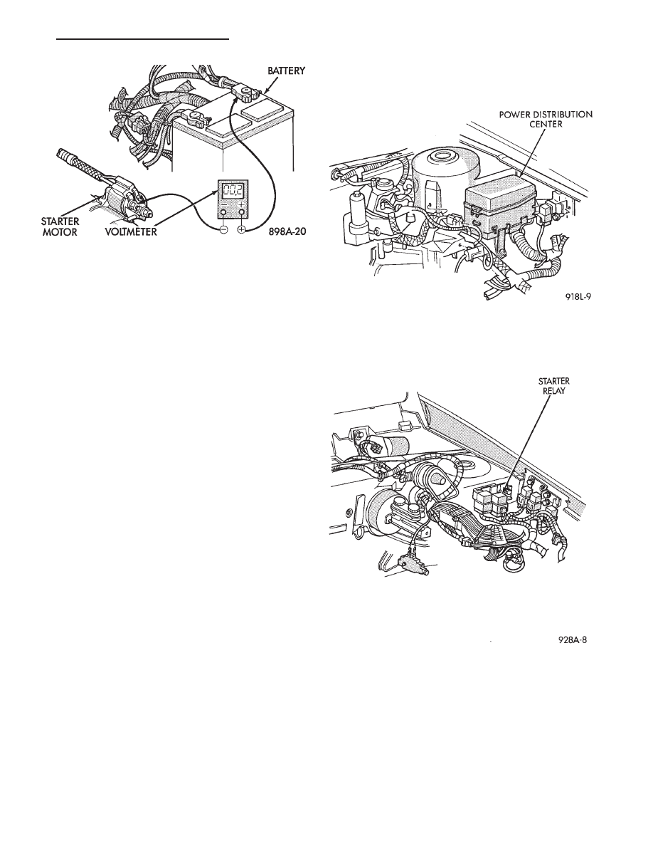
(6) Locate the starter relay as follows:
• On AC, AG, AJ and AY Bodies the relay is located
in the Power Distribution Center. This Center is
mounted near the front of the left front strut tower
(Fig. 13). The position of the starter relay within this
Center will be shown on the Center cover.
• On AA/AP Bodies the relay is located on the front
of the left front strut tower (Fig. 14).
(7) Remove the starter relay from the connector.
(8) Connect a remote starter switch or a jumper
wire between the battery positive post and terminal
87 on the starter relay connector. To decide the
starter relay terminal numbers, refer to the Starter
Relay Tests.
• If engine now cranks, starter/starter solenoid is
good. Go to the starter relay test.
• If engine does not crank with this test, or solenoid
chatters, check wiring and connectors from starter
Fig. 12 Test Positive Battery Cable Resistance
Fig. 13 Starter Relay Location—AC, AG, AJ, and AY
Bodies
Fig. 14 Starter Relay Location—AA/AP Body
Ä
BATTERY/STARTING/CHARGING SYSTEMS DIAGNOSTICS
8A - 15