Chery Tiggo 5 (T21). Manual - part 502
 

  Index      Chery     Chery Tiggo 5 (T21) - service repair manual 2014 year


Search            


Content   ..  500  501  502  503   ..


Chery Tiggo 5 (T21). Manual - part 502


 47–

24

47

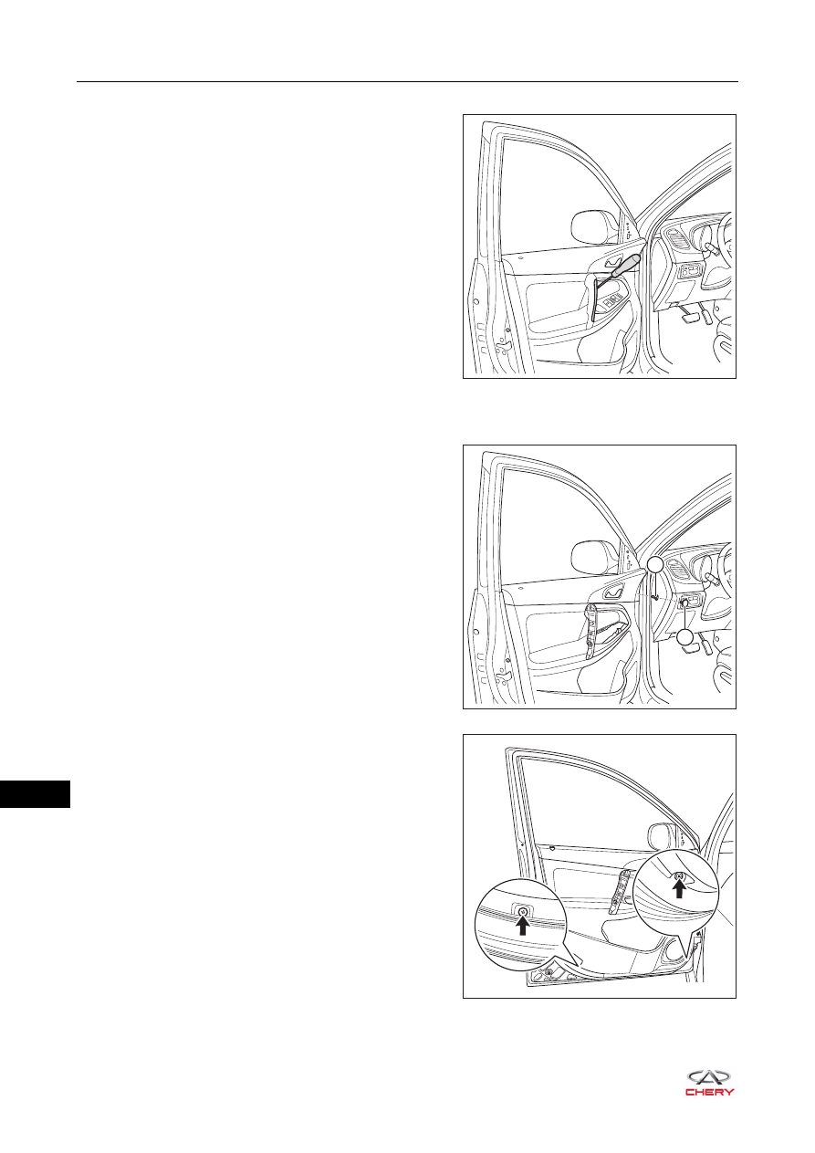
5. Remove the front left door assist grip cover.

a. Using a screwdriver wrapped with protective tape, pry 

up the claws on front left door assist grip cover, and 
remove the front left door assist grip cover.

6. Remove the power glass regulating control master switch assembly (

See page 43-44

).

7. Remove the front left door protector assembly.

a. Using a screwdriver wrapped with protective tape, pry 

up the front door protector screw cover (1).

b. Remove the fixing screw (2) from the upper part of 

front door protector assembly.

(Tightening torque: 1.5 ± 0.5 N·m)

c. Remove 2 fixing screws (arrow) from the lower part of 

front door protector assembly.

(Tightening torque: 1.5 ± 0.5 N·m)

RT21470220

1

2

RT21470240

RT21470250

 47–

25

47

d. Remove 2 fixing screws inside the front door assist 

grip assembly.

(Tightening torque: 1.5 ± 0.5 N·m)

e. Using an interior crow plate, pry off the clips from the 

front door protector assembly, and release the front 
door protector assembly in the direction of arrow as 
shown in the illustration.

f. Disengage the front door inside handle cable (arrow) 

from the slot.

RT21470230

RT21470260

RT21470270

 47–

26

47

g. Disconnect the front door open warning light 

connector (1).

h. Disconnect the anti-theft indicator connector (arrow) 

(for left side).

i. Remove the front left door protector assembly.

8. Remove the front left door inside handle assembly.

a. Remove the fixing screw (arrow) from the front door 

inside handle assembly.

(Tightening torque: 1.5 ± 0.5 N·m)

b. Using a screwdriver wrapped with protective tape, pry 

up the claws on front door inside handle assembly.

c. Remove the front door inside handle assembly from 

the front door protector assembly.

9. Remove the front door assist grip assembly.

a. Remove 4 fixing screws (arrow) from the front door 

assist grip assembly.

(Tightening torque: 1.5 ± 0.5 N·m)

b. Remove the front door assist grip assembly from the 

front door protector assembly.

RT21470280

1

RT21470290

RT21470300

RT21470301

 47–

27

47

10.Remove the courtesy light cover.

a. Using a screwdriver wrapped with protective tape, pry 

up the courtesy light cover.

b. Remove the courtesy light cover from the front door 

protector assembly.

11.Remove the front door courtesy light.

a. Turn the front door courtesy light counterclockwise. 
b. Remove the front door courtesy light from the front 

door protector assembly.

12.Remove the anti-theft indicator.

a. Press the claws (arrow) on anti-theft indicator as 

shown in the illustration.

b. Remove the anti-theft indicator from the front door 

protector assembly.

Installation

Installation is in the reverse order of removal.

RT21470310

RT21470311

RT21470320

CAUTION

 Make sure damaged clips are replaced and front door protector assembly is installed in place when 

installing front door protector assembly. 

 Install connector in place when installing front door protector assembly.
 Make sure each function can operate properly after installing front door protector assembly. 


Content   ..  500  501  502  503   ..