Chery Tiggo 5 (T21). Manual - part 487
 

  Index      Chery     Chery Tiggo 5 (T21) - service repair manual 2014 year


Search            


Content   ..  485  486  487  488   ..


Chery Tiggo 5 (T21). Manual - part 487


45–

26

45

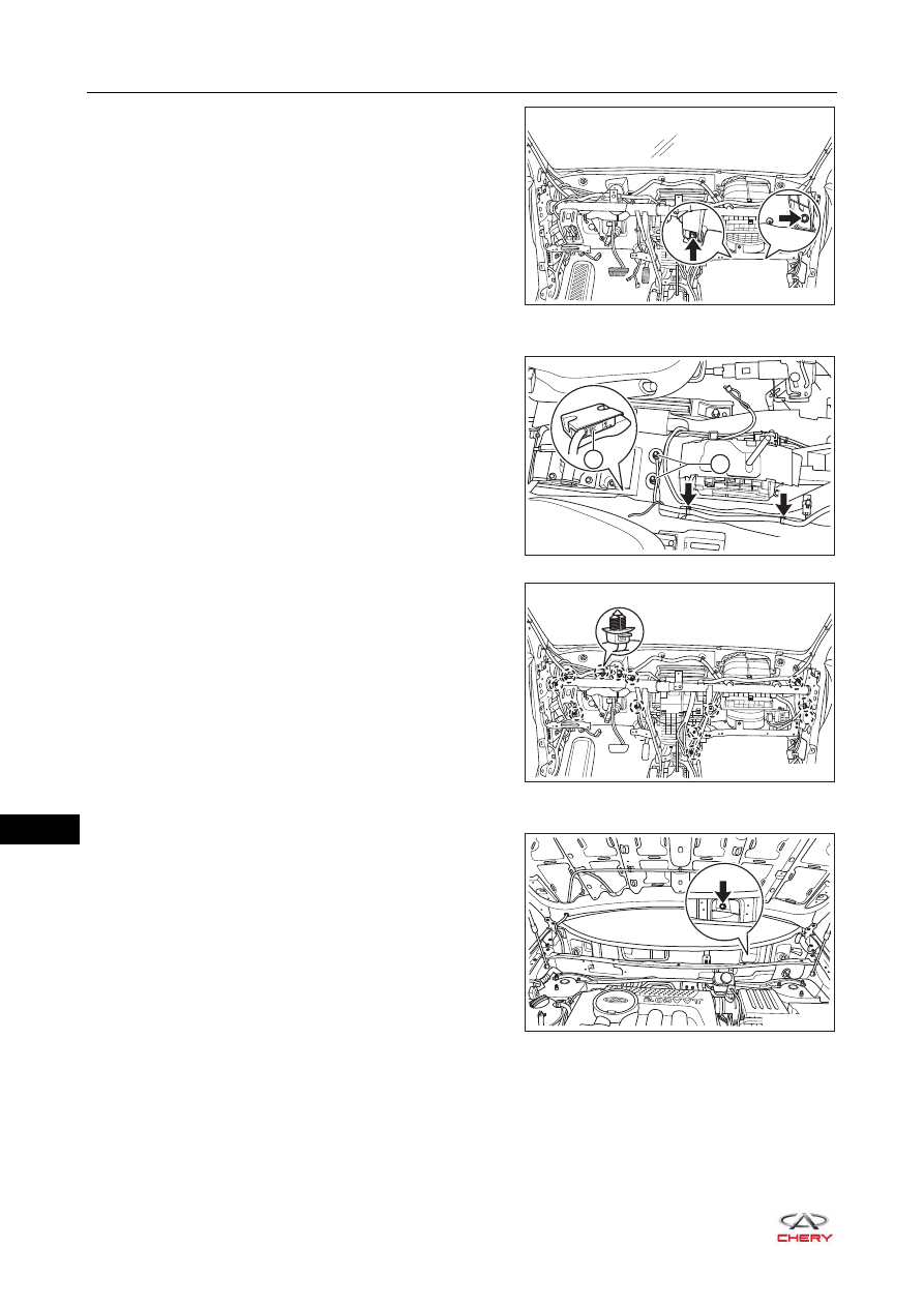
11.Remove 2 fixing bolts (arrow) from blower.

(Tightening torque: 4 ± 1 N·m)

12.Separate the instrument panel wire harness.

a. Disconnect the connector (1) from airbag control 

module.

b. Remove the fixing nuts (2) from ground wire.

(Tightening torque: 15 ± 2 N·m)

c. Remove the clips (arrow) from lower part of 

instrument panel wire harness.

d. Remove the clips from upper part of instrument panel 

wire harness, and separate the instrument panel wire 
harness from instrument panel crossmember.

13.Remove the instrument panel crossmember assembly.

a. Remove the fixing bolt (arrow) from outer part of 

instrument panel crossmember assembly.

(Tightening torque: 25 ± 3 N·m)

RT21450491

2

1

RT21450501

RT21450500

RT21450530

45–

27

45

b. Remove 4 fixing bolts (arrow) from instrument panel 

crossmember assembly.

(Tightening torque: 25 ± 3 N·m)

c. Remove 4 fixing nuts (1) from instrument panel 

crossmember assembly.

(Tightening torque: 7 ± 1 N·m)

d. Remove 2 fixing screws (2) from instrument panel 

crossmember assembly, and remove the instrument 
panel crossmember assembly.

(Tightening torque: 7 ± 1 N·m)

14.Remove the instrument panel crossmember bracket assembly (take left side as an example).

a. Remove 4 fixing bolts (arrow) from instrument panel 

crossmember bracket assembly.

(Tightening torque: 23 ± 2 N·m)

b. Remove the instrument panel crossmember bracket 

assembly.

Installation

Installation is in the reverse order of removal.

RT21450520

2

1

RT21450540

CAUTION

 Make sure to tighten fixing bolts to the specified torque when installing instrument panel crossmember 

assembly.

 Check airbag for proper installation after installing instrument panel crossmember assembly.
 Check each electrical equipment for proper operation after installing instrument panel crossmember 

assembly.

45–

28


Content   ..  485  486  487  488   ..