Chery Tiggo 5 (T21). Manual - part 452
 

  Index      Chery     Chery Tiggo 5 (T21) - service repair manual 2014 year


Search            


Content   ..  450  451  452  453   ..


Chery Tiggo 5 (T21). Manual - part 452


41–

6

41

DIAGNOSIS & TESTING

Problem Symptoms Table

HINT:
Use the table below to help determine the cause of the problem symptoms. Check each suspected area in 
sequence. Repair or replace the faulty components, or adjust as necessary.

Horn Fuse Inspection

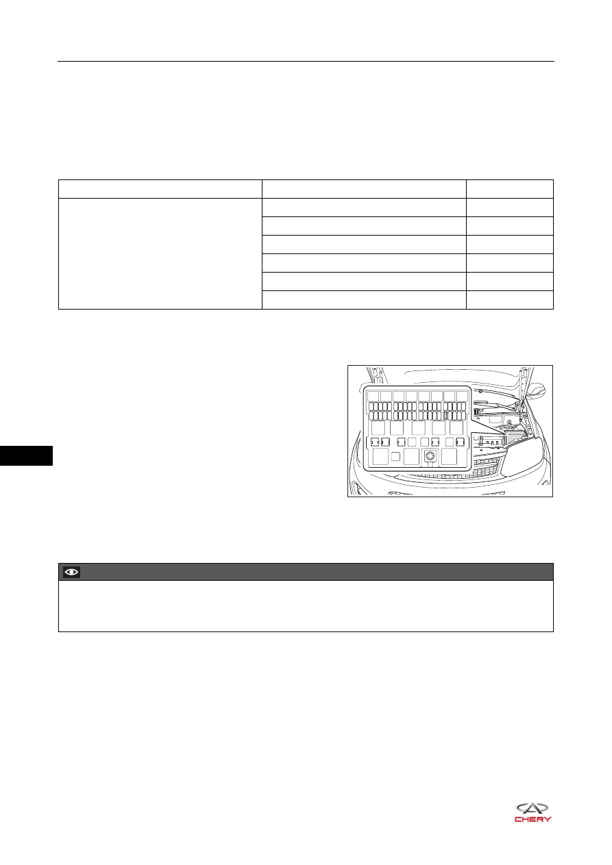
1. Identify the horn fuse on the engine compartment fuse 

and relay box.

2. Check horn fuse.

a. Using a fuse puller, remove the horn fuse (15 A).
b. Check if the fuse is blown. Replace the fuse if it is blown.

Symptom

Suspected Area

See page

Horn does not sound

Horn fuse (blown)

51-34

Low pitched horn (damaged)

41-8

High pitched horn (damaged)

41-8

Horn switch (damaged)

32-65

Spiral cable (damaged)

32-67

Wire harness (short or open)

-

RT21410030

15A

CAUTION

 Use a fuse with the same specification as the original fuse to avoid affecting normal usage of electrical 

equipment.

41–

7

41

Horn Relay Inspection

1. Check horn relay.

a. Remove the relay from engine compartment fuse and relay box.
b. Measure resistance according to the table below.

If result is not as specified, replace the relay.

RT21410031

-

+

1

4

2

5

3

Multimeter 

Connection

Condition

Specified 

Condition

Terminal 3 - 

Terminal 5

When battery 

voltage is not 

applied between 

terminal 2 and 

terminal 1

No continuity

Terminal 3 - 

Terminal 5

When battery 

voltage is applied 

between terminal 

2 and terminal 1

Continuity

41–

8

41

ON-VEHICLE SERVICE

Horn

Removal

1. Turn off all the electrical equipment and ignition switch.
2. Disconnect the negative battery cable.
3. Remove the radiator grille assembly (

See page 41-8

).

4. Remove the high pitched horn.

a. Disconnect the high pitched horn wire harness 

connector (1).

b. Remove the fixing bolt (arrow) from high pitched horn 

bracket, and remove the high pitched horn.

(Tightening torque: 16 ± 2 N·m)

5. Remove the low pitched horn.

a. Disconnect the low pitched horn wire harness 

connector (1).

b. Remove the fixing bolt (arrow) from the low pitched 

horn bracket, and remove the low pitched horn.

(Tightening torque: 16 ± 2 N·m)

Inspection

1. Check high pitched horn.

Apply battery voltage to the high pitched horn and check 
the operation of high pitched horn.

If result is not as specified, replace the high pitched horn.

1

RT21410040

1

RT21410041

-

+

2

1

RT21410050

Measurement 

Condition

Condition

Specified 

Condition

Battery positive 

(+) - Terminal 1

Battery negative 

(-) - Terminal 2

Always

Sounds

41–

9

41

2. Check low pitched horn.

Apply battery voltage to the low pitched horn and check 
the operation of low pitched horn.

If the result is not as specified, replace the high pitched 
horn.

3. Check wire harness.

Using a digital multimeter, check for an open, short or ground failure in the horn system wire harness. 
Replace if necessary.

Installation

Installation is in the reverse order of removal.

-

+

2

1

RT21410060

Measurement 

Condition

Condition

Specified 

Condition

Battery positive 

(+) - Terminal 1

Battery negative 

(-) - Terminal 2

Always

Sounds

CAUTION

 Tighten fixing bolts to the specified torque.
 Install each connector in place.


Content   ..  450  451  452  453   ..