Chery Tiggo 5 (T21). Manual - part 400
 

  Index      Chery     Chery Tiggo 5 (T21) - service repair manual 2014 year


Search            


Content   ..  398  399  400  401   ..


Chery Tiggo 5 (T21). Manual - part 400


35–

75

35

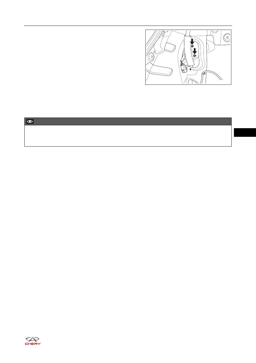
d. Remove 2 fixing nuts (arrow) from inner part of rear 

combination light assembly (fixed part), and detach 
the inner fixing clip.

(Tightening torque: 4.5 ± 1 N·m)

e. Remove the rear combination light assembly (fixed part).

Installation

Installation is in the reverse order of removal.

RT21350260

CAUTION

 When installing rear combination light assembly, make sure the fitting clearance between rear 

combination light assembly and back door, rear bumper is appropriate. Adjust it as necessary.

35–

76

35

Rear Combination Light Assembly (Movable Part)

Removal

HINT:

 Use the same procedures for the right side and left side.

 Procedures listed below are for the left side.
1. Turn off all the electrical equipment and ignition switch.
2. Disconnect the negative battery cable.
3. Remove the rear combination light assembly (movable part).

a. Using a flat tip screwdriver wrapped with protective 

tape, pry up and remove the rear left combination light 
service cover on back door.

b. Disconnect the rear combination light assembly 

(movable part) wire harness connector (arrow), and 
detach the wire harness fixing clip.

c. Remove 3 fixing nuts (arrow) from rear combination 

light assembly (movable part).

(Tightening torque: 4.5 ± 1 N·m)

d. Remove the rear combination light assembly (movable part).

RT21350270

RT21350280

RT21350290

35–

77

35

Installation

Installation is in the reverse order of removal.

CAUTION

 When installing rear combination light assembly, make sure the fitting clearance between rear 

combination light assembly and back door, rear bumper is appropriate. Adjust it as necessary.

35–

78

35

Front Fog Light Assembly

Removal

HINT:

 Use the same procedures for the right side and left side.

 Procedures listed below are for the left side.
1. Turn off all the electrical equipment and ignition switch.
2. Disconnect the negative battery cable.
3. Remove the front wheel house protector assembly (

See page 48-24

).

4. Remove the front fog light assembly.

a. Disconnect the front fog light assembly wire harness 

connector (arrow).

b. Remove 3 fixing crews (arrow) from front fog light 

assembly.

(Tightening torque: 1.5 ± 0.5 N·m)

c. Remove the front fog light assembly.

Installation

Installation is in the reverse order of removal.

RT21350300

RT21350310


Content   ..  398  399  400  401   ..