Chery Tiggo 5 (T21). Manual - part 395
 

  Index      Chery     Chery Tiggo 5 (T21) - service repair manual 2014 year


Search            


Content   ..  393  394  395  396   ..


Chery Tiggo 5 (T21). Manual - part 395


35–

55

35

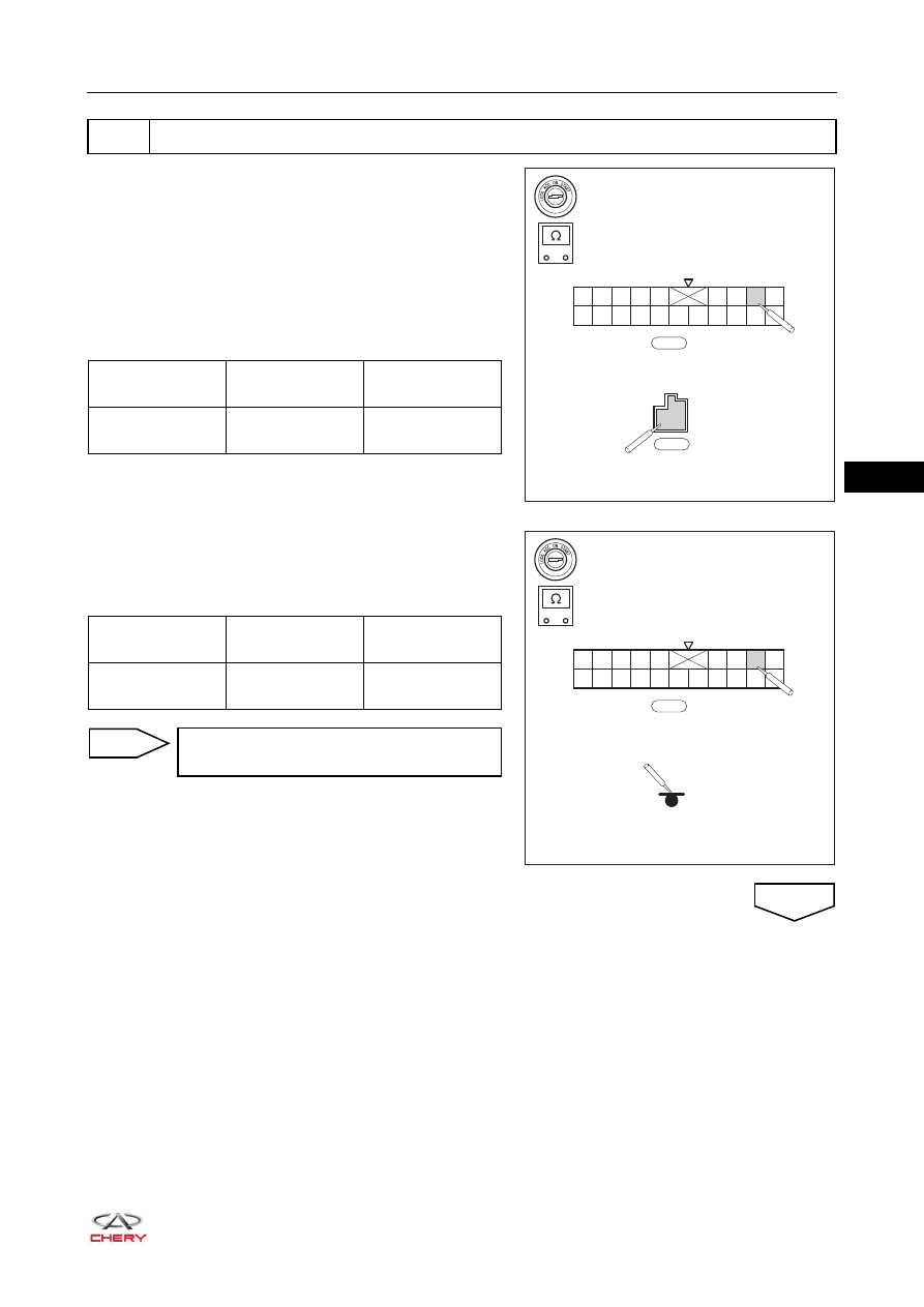
a. Turn ignition switch to LOCK.
b. Disconnect the negative battery cable.
c. Disconnect the Body Control Module (BCM) connectors 

B-043 and E-072.

d. Using a digital multimeter, check for continuity between 

terminal C8 of BCM connector B-043 and terminal E1 of 
BCM connector E-072 to check if it is short to power 
supply according to the table below.
Standard Condition

e. Using a digital multimeter, check for continuity between 

terminal C8 of BCM connector B-043 and body ground to 
check if it is short to ground according to the table below.
Standard Condition

3

Check right position light control circuit

-

+

RT21350660

C1

C10 C11 C12 C13 C14 C15 C16 C17 C18

C2 C3 C4 C5

C6 C7 C8 C9

C20

C19

B-043

E-072

E1

Multimeter 

Connection

Condition

Specified 

Condition

B-043 (C8) - 

E-072 (E1)

Always

No continuity

-

+

RT21350670

C1

C10 C11 C12 C13 C14 C15 C16 C17 C18

C2 C3 C4 C5

C6 C7 C8 C9

C20

C19

B-043

Multimeter 

Connection

Condition

Specified 

Condition

B-043 (C8) - Body 

ground

Always

No continuity

Repair or replace related wire harness and 
connector

NG

OK

35–

56

35

a. Turn ignition switch to LOCK.
b. Disconnect the negative battery cable.
c. Disconnect the Body Control Module (BCM) connector 

B-043.

d. Disconnect the front right headlight wire harness 

connector E-034 and rear right combination light wire 
harness connector B-016.

e. Disconnect the body wire harness connector B-048 and 

engine compartment wire harness connector E-070.

f. Using the digital multimeter, check for continuity between 

terminal C8 of BCM connector B-043 and terminal 15 of 
body wire harness connector B-048 according to the 
table below.
Standard Condition

g. Using a digital multimeter, check for continuity between 

terminal 15 of engine compartment wire harness 
connector E-070 and terminal 8 of front right headlight 
wire harness connector E-034 according to the table 
below.
Standard Condition

4

Check wire harness and connector (right position light - Body Control Module (BCM))

-

+

RT21350680

C1

C10 C11 C12 C13 C14 C15 C16 C17 C18

C2 C3 C4 C5

C6 C7 C8 C9

C20

C19

B-043

1

2

3

4

5

11

12

13

14

15

6

7

8

9

10

22 21 20 19 18 17

16

B-048

Multimeter 

Connection

Condition

Specified 

Condition

B-043 (C8) - 

B-048 (15)

Always

Continuity

-

+

RT21350690

E-070

1

2

3

4

5

6

7

8

9 10

11 12 13 14 15

18

17

16

19 20 21 22

E-034

9

7

5

3

1

10 8

6

4

2

Multimeter 

Connection

Condition

Specified 

Condition

E-070 (15) - 

E-034 (8)

Always

Continuity

35–

57

35

h. Using a digital multimeter, check for continuity between 

terminal C8 of BCM connector B-043 and terminal 6 of 
rear right combination light wire harness connector B-016 
according to the table below.
Standard Condition

i. Disconnect the body wire harness connector B-048 

and engine compartment wire harness connector 

E-070.

j. Using a digital multimeter, check for continuity between 

terminal C8 of BCM connector B-043 and terminal 8 of 
front right headlight wire harness connector E-034 
according to the table below.
Standard Condition

-

+

RT21350700

C1

C10 C11 C12 C13 C14 C15 C16 C17 C18

C2 C3 C4 C5

C6 C7 C8 C9

C20

C19

B-043

1

2

3

4

5

6

B-016

Multimeter 

Connection

Condition

Specified 

Condition

B-043 (C8) - 

B-016 (6)

Always

Continuity

-

+

RT21350710

C1

C10 C11 C12 C13 C14 C15 C16 C17 C18

C2 C3 C4 C5

C6 C7 C8 C9

C20

C19

B-043

E-034

9

7

5

3

1

10 8

6

4

2

Multimeter 

Connection

Condition

Specified 

Condition

B-043 (C8) - 

E-034 (8)

Always

Continuity

Repair or replace related wire harness and 
connector

NG

OK

35–

58

35

a. Firmly reconnect all disconnected connectors.
b. Connect the negative battery cable.
c. Turn ignition switch to ON.
d. Use X-431 3G diagnostic tester (the latest software) to record and clear the DTCs stored in the Body 

Control Module (BCM). 

e. Turn ignition switch to LOCK and wait for a few seconds.
f. Turn ignition switch to ON.
g. Use X-431 3G diagnostic tester to read the DTCs in the Body Control Module (BCM) again.

5

Reconfirm DTCs

Result

Precede to

DTC B100411, B100413 and B100419 are output

NG

No DTC is output

OK

Replace Body Control Module (BCM)

NG

System is normal

OK


Content   ..  393  394  395  396   ..