Chery Tiggo 5 (T21). Manual - part 214
18–
45
18
DTC Confirmation Procedure:
Confirm that battery voltage is between 11 and 14 V before performing the following procedures.
Turn ignition switch to LOCK.
Connect X-431 3G diagnostic tester (the latest software) to Data Link Connector (DLC), and make it
communicate with vehicle electronic module by the data network.
Turn ignition switch to ON.
Using X-431 3G diagnostic tester to record and clear the DTCs stored in the TCU.
Turn ignition switch to LOCK and wait for a few seconds.
Turn ignition switch to ON, and then select "Read Code".
If DTC is detected, the malfunction indicated by the DTC is current. Go to the diagnosis procedure - Step 1.
If DTC is not detected, the malfunction indicated by the DTC is intermittent. Please refer to Intermittent
DTC Troubleshooting.
Diagnosis Procedure
HINT:
After the fault is eliminated, verify DTC and symptom again.
a. Turn ignition switch to LOCK.
b. Disconnect the gear selector connector.
c. Check if the gear selector connector is dirty, oxidized, loose or damaged.
a. Turn ignition switch to LOCK.
b. Disconnect the negative battery cable.
c. Disconnect the transmission range sensor connector and shift the lever to each gear.
d. Check if the terminals of the transmission range sensor connector connects well (
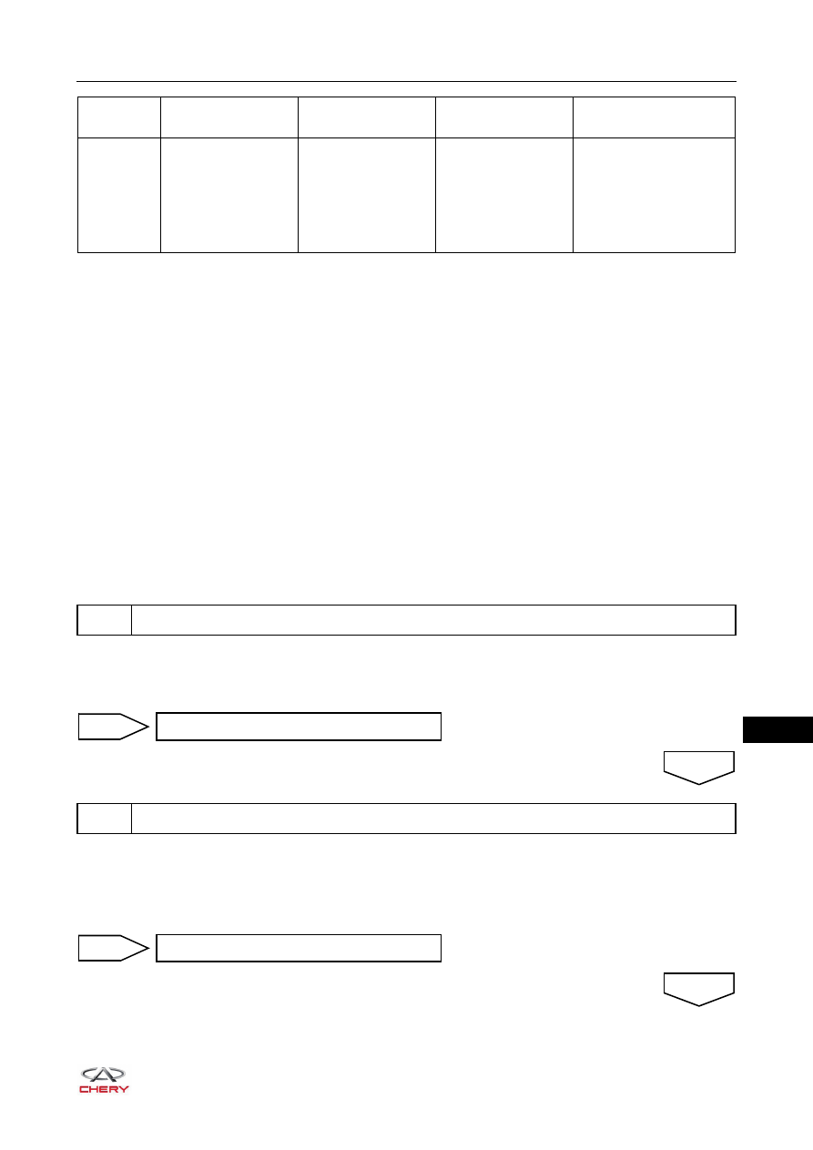
DTC Code
DTC Definition
DTC Detection
Condition
DTC Set Condition
Possible Cause
P0705
Transmission Range
Sensor 'A' Circuit
(P-R-N-D-L Input)
Start engine and
shift between
P-R-N-D-L gears
If multiple TCU
reading gear signals
exist (more than 1)
Transmission range
sensor failure
Gear signal circuit
short circuit to ground
TCU digital signal
circuit failure
1
Check wire harness connector
Repair fault
NG
2
Check transmission range sensor
OK
Replace transmission range sensor
NG
OK