Chery Tiggo 5 (T21). Manual - part 191
 

  Index      Chery     Chery Tiggo 5 (T21) - service repair manual 2014 year


Search            


Content   ..  189  190  191  192   ..


Chery Tiggo 5 (T21). Manual - part 191


17–

18

17

Select and Shift Cable

Removal

1. Turn off all the electrical equipment and ignition switch.
2. Disconnect the negative battery cable.
3. Remove the battery (

See page 16-7

).

4. Remove the air filter assembly (

See page 10-17

).

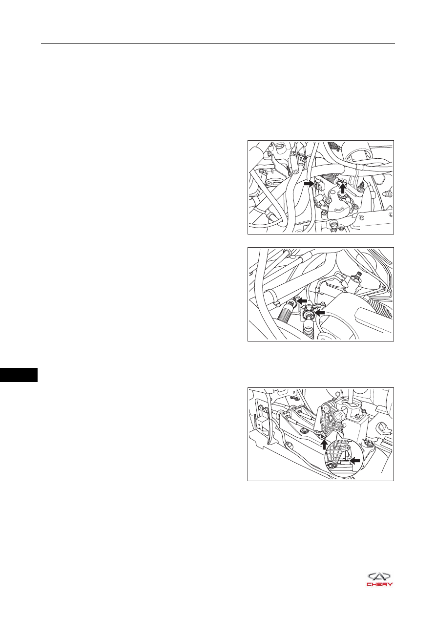
5. Disconnect the select and shift cable from the transmission.

a. Remove the cotter pins (arrow) connecting select and 

shift cable with transmission gear shift mechanism.

b. Remove the flexible shaft clamps (arrow) and select 

and shift cable.

6. Remove the auxiliary fascia console (

See page 45-9

).

7. Remove the fixing bolts between gear select and shift cable and body.
8. Disconnect the select and shift cable from gear shift control mechanism.

a. Remove the flexible shaft clamps and cotter pins 

connecting select and shift cable with gear shift 
control mechanism.

9. Remove the gear select and shift cable.

RT21170090

RT21170100

RT21170110

17–

19

17

Installation

Installation is in the reverse order of removal.

CAUTION

 DO NOT install the select and shift cable in reverse position during installation.

17–

20

17

Gear Shift Control Mechanism

Removal

1. Turn off all the electrical equipment and ignition switch.
2. Disconnect the negative battery cable.
3. Remove the auxiliary fascia console (

See page 45-9

).

4. Remove the gear shift control mechanism.

a. Remove the flexible shaft clamps and cotter pins 

connecting select and shift cable with gear shift 
control mechanism.

b. Remove the fixing bolts from gear shift control 

mechanism, and remove the gear shift control 
mechanism.

(Tightening torque: 23 ± 2 N·m)

Installation

Installation is in the reverse order of removal.

RT21170110

RT21170130

17–

21

17

Transmission Assembly

Removal

1. Turn off all the electrical equipment and ignition switch.
2. Disconnect the negative battery cable.
3. Remove the battery (

See page 16-7

).

4. Remove the battery bracket (

See page 16-9

).

5. Remove the air filter assembly (

See page 10-17

).

6. Drain transmission oil.
7. Remove the front wheels (

See page 24-9

).

8. Remove the drive shaft(

See page 20-5

).

9. Use an engine equalizer to hang the engine.
10.Remove the flexible shaft clamps and cotter pins connecting select and shift cable with gear shift 

mechanism.

11.Disconnect the back-up light switch connector, ground 

wire and clutch line bracket II.

12.Remove the crankshaft position sensor.

a. Remove the fixing bolt from crankshaft position sensor, and remove the crankshaft position sensor.

13.Remove the left mounting (

See page 07-67

).

14.Remove the front mounting (

See page 07-66

).

15.Remove the rear mounting (

See page 07-64

).

16.Remove the clutch release cylinder from transmission (

See page 19-12

).

17.Remove the starter (

See page 15-64

).

18.Remove the transmission.

a. Support the transmission assembly with a 

transmission carrier.

b. Remove the transmission lower coupling bolts, and 

remove the seal plate.

(Tightening torque: 50 ± 5 N·m)

RT21170140

RT21170150


Content   ..  189  190  191  192   ..