Chery Tiggo 5 (T21). Manual - part 175
 

  Index      Chery     Chery Tiggo 5 (T21) - service repair manual 2014 year


Search            


Content   ..  173  174  175  176   ..


Chery Tiggo 5 (T21). Manual - part 175


15–

35

15

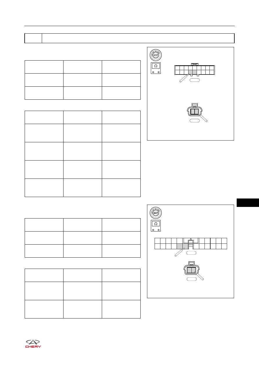
a. Check the body wire harness and connector.

Check for Open

 Check for Short

b. Check the body wire harness and connector.

Check for Open

 Check for Short

3

Check body wire harness and connector

-

+

RT21150271

1

2

B-024

1

2

3

4

5

6

7

8

9

10 11 12 13 14 15 16 17 18

B-059

Multimeter 

Connection

Condition

Specified 

Condition

B-059 (13) - 

B-024 (1)

Always

Continuity

B-059 (14) - 

B-024 (2)

Always

Continuity

Multimeter 

Connection

Condition

Specified 

Condition

B-059 (13) or 

B-024 (1) - Body 

ground

Always

No continuity

B-059 (14) or 

B-024 (2) - Body 

ground

Always

No continuity

B-059 (13) or 

B-024 (1)  -  

Battery positive

Always

No continuity

B-059 (14) or 

B-024 (2) - 

Battery positive

Always

No continuity

B-003

-

+

RT21150280

1

2

B-035

1

2

3

4

5

11

12

13

14

15

16

17 18

19

20

21

22

6

7

8

9

10

Multimeter 

Connection

Condition

Specified 

Condition

B-003 (16) - 

B-035 (1)

Always

Continuity

B-003 (15) - 

B-035 (2)

Always

Continuity

Multimeter 

Connection

Condition

Specified 

Condition

B-003 (16) or 

B-035 (1) - Body 

ground

Always

No continuity

B-003 (15) or 

B-035 (2) - Body 

ground

Always

No continuity

15–

36

15

a. Connect related wire harness connectors.
b. Connect the negative battery cable.
c. Turn ignition switch ON.
d. Connect X-431 3G diagnostic tester to Data Link Connector (DLC) to check if any DTC is detected.

a. Remove the low frequency antenna (

See page 37-54

).

b. Install new low frequency antenna.
c. Connect X-431 3G diagnostic tester to Data Link Connector (DLC) again to check if any DTC is detected.

B-003 (16) or 

B-035 (1)  -  

Battery positive

Always

No continuity

B-003 (15) or 

B-035 (2) - 

Battery positive

Always

No continuity

Repair or replace body wire harness and 
connector

Multimeter 

Connection

Condition

Specified 

Condition

NG

4

Confirm DTCs

OK

System operates normally

OK

5

Replace low frequency antenna

NG

Repair or replace PEPS controller

NG

System operates normally

OK

15–

37

15

SQR484F STARTING SYSTEM

DTC

B1506-00

Abnormality ON Switches of Engine Switch No Subtype 
Information

ET21140080

CVT

J211

1

WL

J210

2

GW

J213

3

L

J204

4

LW

J203

5

RW

J205

8

R

PEPS (J2)

I-030

ENGINE 
SWITCH

I-017

J201

J202

J203

J204

J205

J206

J207

J208

J209

J210

J211

J212

J213

J214

J215

J216

B

I-030

S1

S2

R3

D3 WHITE

D2 GREEN

D1 YELLOW

R6

R2

R5

R1

R4

R9

R8

R7

4

3

2

1

8

7

6

5

W

I-017

15–

38

15

DTC Confirmation Procedure

Confirm that battery voltage is normal before performing the following procedures.
 Turn ignition switch to LOCK.
 Connect X-431 3G diagnostic tester (the latest software) to Data Link Connector (DLC).
 Turn ignition switch ON.
 Use X-431 3G diagnostic tester to record and clear the DTCs stored in the PEPS system.
 Turn ignition switch to LOCK and wait for a few seconds.
 Use X-431 3G diagnostic tester to select "Read Code".
 If DTC is detected, the malfunction indicated by the DTC is current. Go to the diagnosis procedure - Step 1.
 If DTC is not detected, the malfunction indicated by the DTC is intermittent (

See page 15-19

).

Diagnosis Procedure

a. Turn off all the electrical equipment and ignition switch.
b. Disconnect the negative battery cable.
c. Disconnect the PEPS controller connector I-030.
d. Disconnect the engine switch connector I-017.
e. Check if wire harnesses are worn, pierced, pinched or partially broken.
f. Look for broken, bent, protruded or corroded terminals.
g. Check that the related connector pins are in good condition.

DTC Code

DTC Definition

DTC Detection 

Condition

Possible Cause

B1506-00

Abnormality ON 
Switches of Engine 
Switch No Subtype 
Information

Engine switch ON

 Wire harness or connector damaged
 Engine switch
 Passive Entry & Passive Start (PEPS) 

controller

CAUTION

 When performing electrical equipment diagnosis and test, always refer to the circuit diagram for related 

circuit and component information.

1

Check wire harness and connector

Repair or replace related wire harness and 
connector

NG

OK


Content   ..  173  174  175  176   ..