Chery Tiggo 5 (T21). Manual - part 73
 

  Index      Chery     Chery Tiggo 5 (T21) - service repair manual 2014 year


Search            


Content   ..  71  72  73  74   ..


Chery Tiggo 5 (T21). Manual - part 73


06–

134

06

DTC Confirmation Procedure

Confirm that battery voltage is over 12 V before performing the following procedures.
 Turn ignition switch to LOCK.
 Connect X-431 3G diagnostic tester (the latest software) to Data Link Connector (DLC).
 Turn ignition switch to ON.
 Use X-431 3G diagnostic tester to record and clear the DTCs stored in the ECM.
 Start the engine and warm it up to normal operating temperature, and then select Read Code.
 If the DTC is detected, the malfunction indicated by the DTC is current. Go to the diagnosis procedure - Step 1.
 If DTC is not detected, the malfunction indicated by the DTC is intermittent (

See page 06-18

).

Diagnosis Procedure

a. Turn ignition switch to LOCK.
b. Check ECM grounds E-026 and E-028 (

See page 06-18

).

DTC Code

DTC Definition

DTC Detection 

Condition

Possible Cause

P0480-00

Cooling Fan 1 Control 
Circuit

Ignition switch ON

 Cooling fan relay
 Cooling fan controller
 Fuse
 Wire harness or connector
 ECM

P0481-00

Cooling Fan 2 Control 
Circuit

P0691-00

Cooling Fan 1 Control 
Circuit Low

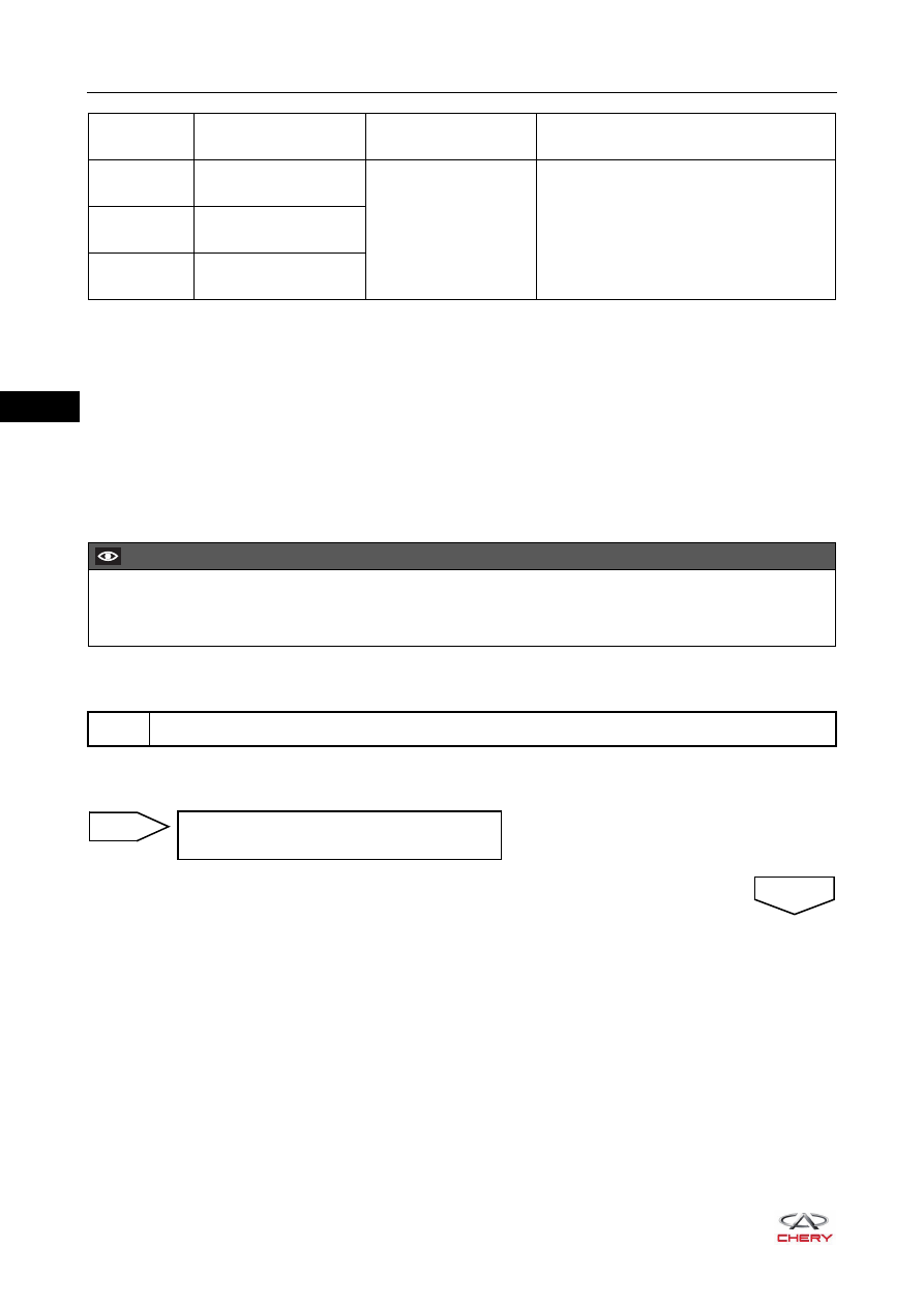
CAUTION

 When performing circuit diagnosis and test, always refer to the circuit diagram for specific circuit and 

component information.

1

Check ECM ground point

Repair or replace ground wire harness or 
ground point

NG

OK

06–

135

06

a. Disconnect cooling fan controller connector E-046.
b. Check cooling fan controller connector.

a. Unplug cooling fan fuse and relay from engine 

compartment fuse and relay box.

b. Check if fuse is normal.
c. Check cooling fan relay.

2

Check cooling fan controller connector

Repair or replace connector

NG

3

Check cooling fan fuse and relay

OK

-

+

85

86

87

30

87

30

85

86

RT21060250

Multimeter 

Connection

Specified Condition

30 - 87

No continuity

30 - 87

Continuity

(when battery voltage is applied 

between terminals 85 and 86)

Replace fuse or relay

NG

OK

06–

136

06

a. Check terminal voltage of cooling fan relay (engine 

compartment fuse and relay box side).

a. Disconnect fuse and relay box connector E-059.
b. Disconnect ECM connector E-033.
c. Check wire harness between fan controller connector 

and ECM connector, engine compartment fuse and relay 
box connector and body ground. 
Check for Open

Check for Short

4

Check cooling fan relay circuit voltage

RT21060260

-

+

V

87

30

85 86

Multimeter 

Connection

Condition

Specified 

Condition

Terminal 87 - 

Body ground

Always

11 to 14 V

Terminal 86 - 

Body ground

Ignition switch ON

11 to 14 V

Terminal 85 - 

Body ground

Always

0 V

Check engine compartment fuse and relay 
box, repair or replace wire harness or 
connector (fan relay - battery)

NG

5

Check wire harness and connector

OK

E-046

E-033

49 50 51

63

64

15

16

31

32

47

48

33 34 35

17 18 19

1 2 3

52 53 54 55 56 57 58 59 60 61 62

36 37 38 39 40 41 42 43 44 45 46

20 21 22 23 24 25 26 27 28 29 30

4 5 6 7 8 9 10 11 12 13 14

1

2

3

-

+

RT21065050

Multimeter Connection

Specified 

Condition

E-033 (56) - E-046 (2)

Continuity

Multimeter Connection

Specified 

Condition

E-033 (56) or E-046 (2) - Body ground

No continuity

E-033 (56) or E-046 (2) - 

Battery positive

No continuity

06–

137

06

Check for Open

Check for Short

a. Use X-431 3G diagnostic tester to read the ECM DTC.
b. Refer to "DTC Confirmation Procedure".
c. Check if DTC P0480-00, P0481-00 or P0691-00 still exists.

2

E-059

E-046

1

2

3

RT21065051

-

+

Multimeter Connection

Specified 

Condition

E-059 (2) - E-046 (1)

Continuity

E-046 (3) - Body ground

Continuity

Multimeter Connection

Specified 

Condition

E-059 (2) or E-046 (1) - Body ground

No continuity

E-059 (2) or E-046 (1) - 

Battery positive

No continuity

Repair or replace wire harness or 
connector

NG

OK

Replace cooling fan controller, and go to step 6

6

Check for DTCs

Replace ECM

NG

System is operating normally.
Reassemble vehicle and perform a road test to confirm that malfunction reported by customer has 
been repaired.

OK


Content   ..  71  72  73  74   ..