Chery Tiggo. Manual - part 279
Diagnostic Procedure
1.
CHECK A/T OUTPUT SIGNAL
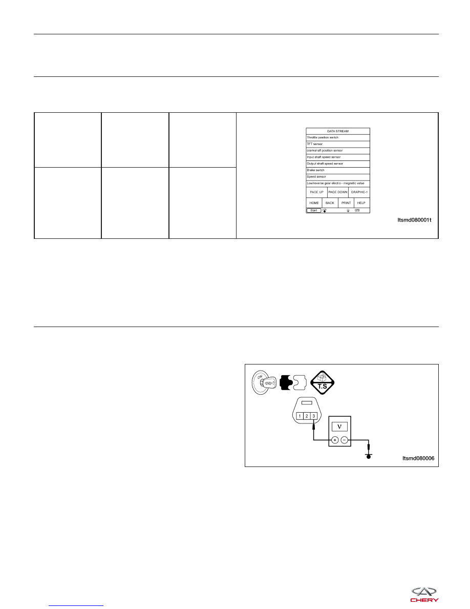
• With the scan tool, select view DTC and data stream for A/T.
• Vehicle start and read out the value of ⬙OUTPUT SPEED SENSOR⬙.
ITEM
CONDITION
DISPLAY
VALUE
Output speed
sensor
During driving
Approximately
matches the
speedometer
reading.
Is the check result normal?
Yes
>>
The condition that caused this DTC is intermittent (See Diagnostic Help in Section 08 Transaxle &
Transfer Case).
No
>>
Go to the next step.
2.
CHECK OUTPUT SHAFT SPEED SENSOR POWER SUPPLY
• Stop vehicle and turn ignition switch off.
• Disconnect output shaft speed sensor connector.
• Turn ignition switch on.
• Check sensor power supply between sensor termi-
nal 3 and ground in the sensor electrical connector
E-089.
• Voltage should be more than 12 V.
Is the check result normal?
Yes
>>
Go to step 4.
No
>>
Go to the next step.
DIAGNOSIS & TESTING
LTSMD080006