Chery Tiggo. Manual - part 123
 

  Index      Chery     Chery Tiggo - service repair manual 2009 year


Search            


Content   ..  121  122  123  124   ..


Chery Tiggo. Manual - part 123


Diagnostic Procedure

1.

CHECK GROUND CONNECTIONS

• Turn ignition switch off.

• Loosen and retighten ground screws on the body (See Ground Inspection in Section 03 Electronic Engine Con-

trols).

• Inspect ground connections E-207 and E-208 mounting position (See Vehicle Wiring Harness Layout - Engine

Room Harness (With 1.6L/1.8L Engine) in Section 16 Wiring).

Are the ground connections OK?

Yes

>>

Go to the next step.

No

>>

Repair or replace ground harness or connections.

2.

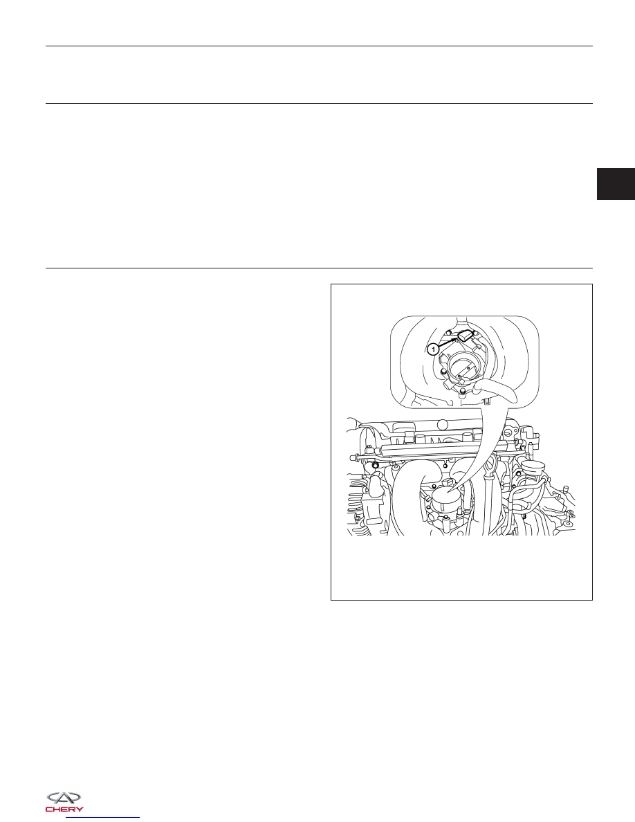
CHECK THROTTLE POSITION SENSOR (TPS) ELECTRICAL CONNECTOR

• Disconnect the TPS (1) electrical connector.

• Inspect the electrical connector for damage.

Is the electrical connector OK?

Yes

>>

Go to the next step.

No

>>

Repair or replace the electrical connector

as necessary.

DIAGNOSIS & TESTING

VISMD030203

03


3.

CHECK THE THROTTLE POSITION SENSOR (TPS) POWER SUPPLY CIRCUIT - (1)

• Turn ignition switch on.

• Check supply voltage between TPS terminal 3 and

ground in the TPS electrical connector E-027.

• Approximately 5 V should exist.

Is the check result normal?

Yes

>>

Go to step 8.

No

>>

Go to the next step.

4.

CHECK THE TPS POWER SUPPLY CIRCUIT - (2)

• Turn ignition switch off.

• Disconnect ECM harness connector.

• Check harness continuity between TPS terminal 3 and ECM terminal 32.

• Continuity should exist.

Is the check result normal?

Yes

>>

Go to the next step.

No

>>

Repair or replace circuit for an open.

5.

CHECK THE TPS POWER SUPPLY CIRCUIT - (3)

• Check harness for short to power or short to ground, between following terminals.

ECM TERMINAL

TPS TERMINAL

32

TPS terminal 3

32

APP sensor terminal 3

33

APP sensor terminal 6

Is the check result normal?

Yes

>>

Go to the next step.

No

>>

Repair circuit for short to ground or short to power in harness or connectors.

DIAGNOSIS & TESTING

LTSMD030035


6.

CHECK THE ACCELERATOR PEDAL POSITION (APP) SENSOR

• Connect all harness connectors disconnected.

• Turn ignition switch on.

• Check voltage between ECM terminals 16 (APP sensor 1) and ground, terminal 40 (APP sensor 2) and ground

under the following conditions:

ECM TERMINAL

APP SENSOR

TERMINAL

16

APP sensor terminal

4

40

APP sensor terminal

1

ECM TERMINAL

NO.

ITEM

CONDITION

DATA (DC

VOLTAGE)

16

Accelerator Pedal
Position Sensor 1

(APPS1)

Turn ignition switch

on

• Engine stopped

• Accelerator pedal:
Fully released

0.72 - 0.74 V

• Engine stopped

• Accelerator pedal:
Fully depressed

3.95 V

40

Accelerator Pedal
Position Sensor 2

(APPS2)

• Engine stopped

• Accelerator pedal:
Fully released

0.36 - 0.37 V

• Engine stopped

• Accelerator pedal:
Fully depressed

1.97 V

Is the check result normal?

Yes

>>

Go to step 10.

No

>>

Replace the Accelerator Pedal Assembly (See Accelerator Pedal Position Sensor Removal & Installation

in Section 03 Electronic Engine Controls).

7.

CHECK THE TPS SIGNAL CIRCUIT FOR AN OPEN OR SHORT

• Turn ignition switch off.

• Disconnect ECM harness connector.

• Check harness continuity between electronic throttle control actuator terminal 5 and ECM terminal 38, electronic

throttle control actuator terminal 6 and ECM terminal 54.

• Continuity should exist.

• Check harness for short to power and short to ground.

Is the check result normal?

Yes

>>

Go to the next step.

No

>>

Repair circuit for an open or short to power or short to ground in harness or connectors.

DIAGNOSIS & TESTING

03


8.

CHECK THE TPS GROUND CIRCUIT FOR AN OPEN OR SHORT

• Check harness continuity between electronic throttle control actuator terminal 2 and ECM terminal 78.

• Continuity should exist.

• Check harness for short to power and short to ground.

Is the check result normal?

Yes

>>

Go to the next step.

No

>>

Repair circuit for an open or short to power in harness or connectors.

9.

CHECK TPS

• Connect all harness connectors disconnected.

• Turn ignition switch on.

• Check voltage between ECM terminals 54 (TP sensor 1) and ground, terminal 38 (TP sensor 2) and ground

under the following conditions:

ECM

TERMINAL

NO.

ITEM

CONDITION

DATA (DC

VOLTAGE)

38 (TPS

connector

terminal 5)

Electronic

throttle
control

actuator

(Position

sensor)

Ignition
switch
on

• Engine
stopped

• Accelerator

pedal: Fully
released

4.24 V

• Engine
stopped

• Accelerator

pedal: Fully
depressed

0.72 V

54 (TPS

connector

terminal 6)

Electronic

throttle
control

actuator

• Engine
stopped

• Accelerator

pedal: Fully
released

0.74 V

• Engine
stopped

• Accelerator

pedal: Fully
depressed

4.62 V

Is the check result normal?

Yes

>>

Go to the next step.

No

>>

Replace electronic throttle control actuator, and perform throttle valve position learning.

DIAGNOSIS & TESTING


Content   ..  121  122  123  124   ..