Chery Tiggo. Manual - part 16
 

  Index      Chery     Chery Tiggo - service repair manual 2009 year


Search            


Content   ..  14  15  16  17   ..


Chery Tiggo. Manual - part 16


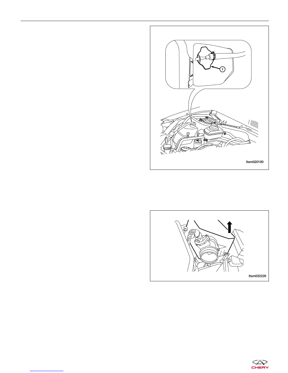
7. Remove coolant reservoir (1).

8. Remove the coolant fan & radiator assembly (See Coolant Fan & Radiator Assembly Removal & Installation in

Section 06 Cooling).

9. Remove the starter motor wiring.

10. Relieve the fuel pressure (See Fuel Pressure Relief Procedure in Section 04 Fuel Delivery).

11. Disconnect and remove the fuel line at the fuel rail.

12. Remove the air inlet hose and the air cleaner case

assembly.

NOTE: For 1.8L engine, disconnect the air flow
sensor electrical connector.

13. Remove the ground cable bolt from the cylinder head.

ON-VEHICLE SERVICE

LTSM020190

LTSM020226


14. Disconnect and remove the following electrical connectors:

€ Coolant temperature sensor
€ Camshaft position sensor
€ Ignition coil
€ Four fuel injectors
€ Intake manifold air pressure sensor (1.6L)
€ Air flow sensor (1.8L)
€ Carbon canister solenoid valve
€ Throttle body control
€ A/C compressor
€ Oil pressure sensor
€ Power steering pump pressure switch
€ Generator

15. Remove the pipe from the canister control valve

(1).

16. Disconnect the heater hoses (1) on the vehicle.

17. Remove the vacuum line from the brake booster

(2).

18. Remove the dipstick.

19. If equipped with a manual transaxle remove the

transaxle shift cable (1).

ON-VEHICLE SERVICE

LTSM020235

BESM020025

BESM080051

02


20. If equipped with an automatic transaxle, remove

the transaxle shift cable (1) and the transaxle shift
cable clamp (2).

21. Remove the hydraulic pipe from the clutch slave

cylinder.

22. Remove the A/C compressor line bolt (1) from the

A/C compressor.
(Tighten: A/C compressor line bolts to 20 N·m)

NOTE: After removing the A/C lines, plug the A/C
lines to prevent any debris from entering the A/C
system.

23. Remove the high pressure line (1) and low pres-

sure line (2) from the power steering pump (drain
fluid from lines).
(Tighten: High pressure line to power steering
pump 40 ± 5 N·m)
(Tighten: Low pressure line to power steering pump
40 ± 5 N·m)

24. Remove the exhaust manifold heat shield bolts (1)

and then remove heat shield.
(Tighten: Exhaust manifold heat shield bolts to 15
N·m)

25. Disconnect the upstream and downstream oxygen sensor connectors.

ON-VEHICLE SERVICE

LTSM080186

VISM130017

BESM110011

BESM020078


26. Remove the catalytic converter to exhaust manifold

bolts (1).

27. Raise and support the vehicle.

28. Remove the front axle shaft (See Front Axle Shaft Removal & Installation in Section 09 Driveline & Axle).

29. Drain the engine oil.

30. Lower the vehicle and install engine lift chain hangers.

31. Remove the bolts (1) securing the front engine

mount.
(Tighten: Engine front mount bolt to 60 N·m)

32. Remove the bolts (1) securing the rear engine

mount.
(Tighten: Engine rear mount bolt to 60 N·m)

ON-VEHICLE SERVICE

LTSM020201

BESM080035

LTSM020207

02


Content   ..  14  15  16  17   ..