Chery S11 / Chery QQ. Manual - part 209
 

  Index      Chery     Chery S11 / Chery QQ - service repair manual


Search            


Content   ..  207  208  209  210   ..


Chery S11 / Chery QQ. Manual - part 209


 Chery  QQ  Maintenance Manual                     372 EFI System


主继电器

喷油器组


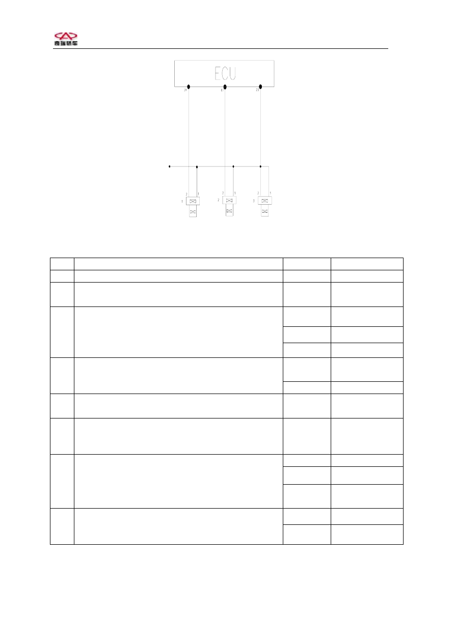
The diagram of injector   
 

No.   

Operation steps 

Test result  Next step 

Turn on ignition key without engine run. 


Next 

Put out al connectors on injector harness; connect two 
probes of multimeter on pin 1 and engine ground. 

 Next 

Yes 

Repeat step 2 

Yes 6 

Turn on ignition key. See if the display on multimeter 
is 12 V for 1 second once turning on the key. 

No Next 

Yes 

Repair or replace 

harness 

Use multimeter to check if    open or short between 
pin 87 on pump relay output and pin 1 on each 
injector. 

No  

Next 

Repair or replace pump replay, main repalay and 
circuit. 

Yes 

Repair or replace 

harness 

Connect the adaptor between ECU and harness. 
Check if open or short between pin 24, pin 61, pin 23 
on ECU and pin 2 on each injector separately. 

No Next 

Yes 

Repeat step 7 

Yes Next 

Use multimeter to check if resistance between pin 1 
and pin 2 on injector is 12—16V in 20 C


No  

Replace  

injector 

Yes 

Repeat step 8 

Reinsert all injector connector. Put N shaft and run 
engine in idle. Put out each injector connector in turn 
and check if the vibration of engine becoe serious. 

No Replace 

ECU 


 Chery  QQ  Maintenance Manual                     372 EFI System


                                                        Canistor control driver 

    Diagram 

of canistor control valve 


No. Operation 

steps 

Test 
result 


Next step 

Run engine in idle to normal coolant 
temperature.  

 Next 

Yes Next 

Put out the connector on canistor valve and 
check if the voltage between two pins is 12 
V. 

No 5(Check live 

wire) 

Yes Next 

Reinsert conncetor of canistor valve 
harness. Run engine to 1500 RPM. Touch 
valve with hand and check if any slightly 
viabration or impact on valve. 

No 7(Check ground 

wire) 

Yes ReplaceECU 

Use multimeter to check if resistance 
between pin 1 and pin 2 is 22—30. 
 

No   Replace canister 

control valve 

Yes 

Repair or replace 

harness 

Use multimeter to check if open or short 
between pin 87 on main relay and pin 1 on 
valve. 

No Next 

Repair or replace main relay and circuit. 


Yes 

Repair or replace 

harness 

Shut off engine. Connect adaptor between 
ECU and harness. Use multimeter to check 
if open or short between pin 26 on ECU and 
pin 2 on valve. 

No Replace 

ECU 


 Chery  QQ  Maintenance Manual                     372 EFI System


MIL driver 


The diagram of MIL 


NO.  

Operation steps 

Test 
result 


Next step 

Turn on ignition key 


Next 

Yes Next 

Remove instrument panel. Put out MIL 
bulb. Use multimeter to check if the voltage 
in MIL socket is 12 V. 
 

No 5(Check live 

wire) 

Yes Next 

Use multimeter to check if MIL bulb is 
good. 
 

No Replace 

bulb. 

Yes 

Repair or replace 

harness 

Connect the adaptor between ECU and 
harness. Check if open or short between pin 
70 on ECU and input connector of MIL. 

No Replace 

ECU 

Yes Replace 

fuse 

Check if the fuse in oxygen heating circuit 
is burn out. 

No Next 

Yes 

Repair or replace 

harness 

Use multimeter to check if open or short 
between pin 87 on main relay and pin 1 on 
MIL socket. 

No Next 

Repair or replace main relay and circuit. 


 Chery  QQ  Maintenance Manual                     372 EFI System


No. 1 and No.2 coil driver in step motor 


怠速步进电机


The diagram of idle actuator/step motor 
 

No. Operation 

steps Test 

results 


Next step 

Turn on ignition key but engine not run. 


Next 

Yes Next 

Put out the connector on step motor    and 

check if the resistance between pin 1, pin 

2,and pin 3, pin 4 is 40—80. 

No Replace 

idle 

actuator  

Yes Next 

Use multimeter to check if the resistance 

between pin 1 and pin 2 as well as Pin 3 and 

pin 4 are infinite. 

No 

Replace bulb or 

actuator 

Yes Replace 

actuator 


Use multimeter to check if voltages between 

pin 1 and pin 2 as well as pin 3 and pin 4 are 

12V


No Next 

Yes 

Repair or replace 

harness 


Connect adaptor between ECU and harness. 

Use multimeter to check if open or short 

between pin 19,pin 20, pin 35, pin 36 on ECU 

and pin1,2,3,4 on step motor. 

No Replace 

ECU 


6. The diagnosis steps according to engine symptoms 
Before beginning diagnosis steps according to engine symptoms, the primary checking should 


Content   ..  207  208  209  210   ..