Chery S11 / Chery QQ. Manual - part 192
 

  Index      Chery     Chery S11 / Chery QQ - service repair manual


Search            


Content   ..  190  191  192  193   ..


Chery S11 / Chery QQ. Manual - part 192


Chery    QQ    Maintenance Manual                                            Chassis System 

 
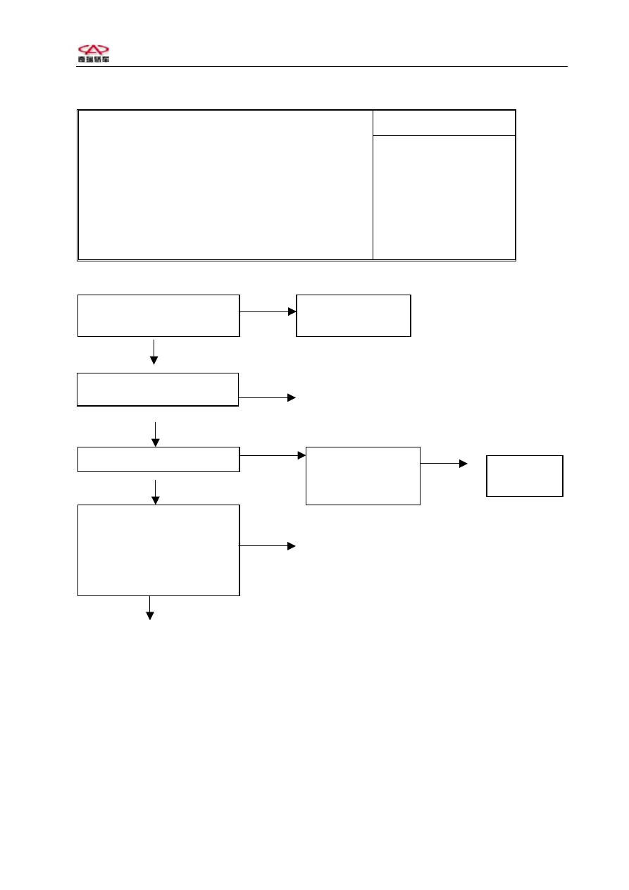
6、No DTC put out( cannot communicate with tester) 

Possible cause 

Open in ABS ECU source circuit or diagnosis 

circuit 

·Fuse burn out 

·Diagnosis wire 

loose or damage 

·ABS ECU damage 

·Tester problem 


No


Yes


Fix tester and try

again 

Can tester communicate with

other MK20 ABS ECU 

Abnorma


Replace


Check ABS fuse 

Norma


No


Abnorma


Yes

On 


No 

Fix diagnosis plug or harness   


Any display on tester 

Check source wire,

ground wire, and

connector 

Check terminal is conducted

with diagnosis terminal
(MK20I/E : terminal 7) 

Fix or

replace 

    
Replace ABS ECU 


50


Chery    QQ    Maintenance Manual                                            Chassis System 

 
8、ABS inspection 

Terminal 

Item 

Key 
position  MK20I/E 

Specifications  Unit 

Battery and motor 
voltage 

OFF 

25-8 

10.1-14.5 

Battery and solenoid 
voltage 

↑ 

9-24 

↑ 

Source isolation 

↑ 

8-4 

0.00-0.5 

Ground isolation 

↑ 

8-24 

↑ 

Source 

ON 

8-4 

10.0-14.5 

OFF 

Light off 


ON 

ECU not 
connected 

Light on 


OFF 

Light off 


ABS light 

ON 

Connect ECU 

Light on for 1.7 
sec and off 


Brake light pedal not 
push down 

ON 

8-18 

0.0-0.5 

Brake light pedal 
push down 

ON 

8-18 

10.0-14.5 

Front left sensor 
resistance 

OFF 

1-2 

1.0-1.3 

KΩ 

Front right sensor 
resistance 

OFF 

19-20 

1.0-1.3 

KΩ 

Rear left sensor 
resistance 

OFF 

5-6 

1.0-1.3 

KΩ 

Rear right sensor 
resistance 

OFF 

22-23 

1.0-1.3 

KΩ 

Front left sensor out 
put voltage 

OFF 

1-2 

3.4-14.8 

mV/HZ 

Front right sensor 
resistance out put 
voltage 

OFF 

19-20 

3.4-14.8 

mV/HZ 

Front left sensor out 
put voltage 

OFF 

5-6 

>12.2 

mV/HZ 

Rear left sensor out 
put voltage 

OFF 

22-23 

>12.2 

mV/HZ 

Sensor out put 

voltage ratio 

Max peak voltage 


    ≦ 2 

Min peak voltage 


51


Chery    QQ    Maintenance Manual                                            Chassis System 


9、Check ABS 
(1) Check the out put voltage of speed sensor 
1. Check if the clearance between speed sensor and teeth ring is satisfied with 
specification. 
2. Lift the wheel and release manual brake. 
3. Remove ABS harness and measure the points of connector. 
4. Run the wheel at speed of 1/2 RPM and measure the out put voltage. 
             MK20 I                                  MK20 I/E 
Front left wheel terminal 4 – 11       terminal 1 - 2 
Front right wheel terminal 3 – 18      terminal 19 – 20 
Rear left wheel terminal 2 – 10        terminal 5 - 6 
Rear right wheel terminal 1 – 17       terminal 22 – 23 
5. If the voltage is not with specification, the causes may be: 

 The clearance between sensor and teeth ring is too big. 
 Sensor malfunction. 
 The resistance of sensor is 1.0—1.3 k. 
 Distortion of teeth ring. 

 
10、Removal and installation 
(1)、 Spare parts offering  
* HECU assembly dry type; 
* HCU  and ECU  separate HCU  wet type 
(2)、Precaution on removing 

 Repair the faults after find the 

 cause for malfunction with test  
instrument 


 Only open the package before  

installation. 

 Only use original parts. 
 Only clean with soft cloth. 
 Don’t use compressed air or move the 

vehicle when ABS is working. 

 Block the outlet for each pipe after 

removing the parts. 

 Please use DOT 4 brake fluid. 
 Dip the seal and o-ring with brake liquid. 
 Check the function of ABS and conventional brake system is normal after 

repairing. 

 Check if any leakage on each connector. 

(3)、MK20-I HECU assembly Removal  

 Turn off ignition switch and disconnect (-) wire on battery. 
 Remove the harness from ABS assembly. 


52


Chery    QQ    Maintenance Manual                                            Chassis System 


 Put down pedal >60mm and fix with bracket to prevent liquid flow out. 
 Remove the brake pipe AB on master cylinder and marked with dot. Block the 

outlet with rubber cover. 

 Remove brake liquid pipe 1—4 and marked with dot. Block the outlet with rubber 

cover. 

 Loosen the bolts fixing HECU to support. 
 Remove HECU from support. 

(4)、Replace HECU 

 Remove the harness of pump motor. 
 Remove 4 bolts and don’t reuse. 
 Separate HCU and ECU. 
 Install new HCU on ECU.  
 Screw the bolts fixed HCU on ECU with torque 3+1 Nm. 
 Insert the harness of motor. 

2
3

1

B

A

(5)、Replace ECU 

 Remove the harness. 
 Remove 4 bolts and don’t reuse. 
 Remove HCU from ECU. 
 Install new HCU on ECU. 
 Screw the bolts fixed HCU on ECU with 

torque 3+1 Nm.  

 Insert the harness of motor. 

(6)、Install ABS assembly again 
Attention:Only remove the cover on hydraulic 
outlet while install the brake pipe to prevent 
the matter dropping into system. 

 Install ABS assembly on support with torque 20+4Nm. 

A  前活塞 B  后活塞 

1  右前轮    2    左后轮     

3

右后轮

4

左前轮

A.Front piston;  B.Rear piston 

1.Right front wheel;2.Left rear wheel 

3.Right rear wheel;4.Left front wheel 

 Remove the cover on hydraulic outlet and install brake pipe with torque 12+4Nm 

M10×1 and 15+3Nm M12×1. 

 Make sure the pipe is installed correctly. 
 Charge new brake fluid to MAX position and exhaust gas according to 

specification. 

 Turn on ignition switch, ABS warning light will be up for 1.7 second and turn 

off. 

 Clear DTC. 
 Drive the vehicle to confirm the function of ABS and feel pedal is rebound. 

 
11、ABS ECU Socket 


53


Content   ..  190  191  192  193   ..