Chery S11 / Chery QQ. Manual - part 185
 

  Index      Chery     Chery S11 / Chery QQ - service repair manual


Search            


Content   ..  183  184  185  186   ..


Chery S11 / Chery QQ. Manual - part 185


Chery    QQ    Maintenance Manual                                            Chassis System 


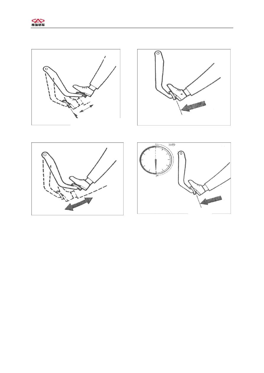
3、When the engine is running, step 
on the brake pedal, and stop the 
engine while stepping on the brake 
pedal. 
4、Step on the pedal and keep for 30 
seconds. 
If there is no replace in the pedal 
height,  it  means  the  operation  is 
normal. If the pedal rises, it means 
the operation is not normal. 
Attention:If the checks fail, the 
inspections on the vacuum tube and 
sealing parts will be needed. 
Make proper replacements of the def- 
ective parts. Repeat all the tests 
after replacing the parts. 


Steps of installation 

Holding 

Onc

e,

 Twi

ce,

 Threetimes


Holding 

1. Align 4 bolts on vacuum booster in 
left engine compartment to 4 holes on 
front board. 
2. Screw 4 bolts with torque 25±
2N.m. 
3. Use pins to connect the pedal and 
vacuum booster lever and install 
pins. 
4. Install brake light switch. 
Adjust the position of light. Insert 
switch connector. 
5. Install master cylinder and 
perorational valve to the booster. 
Screw 2 bolts with 16N.m. 
7. Connect vacuum hose on thebo- 
oster. 


22


Chery    QQ    Maintenance Manual                                            Chassis System 


8、Description and operation 

1)Brake gross pump 
Points of attention 

 Use clean fluid to lubricate 

rubber parts for easily mounting. 

 Don’t use compressed air with 

lubricant on brake parts. 

 Drain out air for whole or partial 

system after removing any hydr- 

 aulic parts. 
 The specified torque is used in 

dry fixture. 

  Operate on the clean desk without mineral 

oil. 

The master cylinder consists of 

plastic reservoir and aluminum shell. 
The primary piston is used for front 
brake and rear brake. Secondary pis- 
ton is used other front brake and rear 
brake. Fluid level sensor in mounted 
on reservoir. Proportional valve is 
mounted below master cylinder. The 
valve is used to offer better balance 
for front/rear brake in heavy load. 
Proportioning valve 
Points of attention 

Don’t clean the valve in any 

washing fluid.The valve is below 
master cylinder. Fluid will damage 
paint and electric element. Resin the 
parts if fluid sprayed on vehicle. 
Level sensor 
Level sensor in mounted in master 
cylinder. Sensor switch is in rese- 
rvoir. If the level is too low, sensor 
will turn warning light on. When the 
level is correct, light is off.Please 
see “ Brake warning system” in 
“ Diagnosis for electric system”. 


23


Chery    QQ    Maintenance Manual                                            Chassis System 


2) Vacuum actuator description 
Points of attention 

 Use clean fluid to lubricate 

rubber parts for easily mounting. 

 Don’t use compressed air with 

lubricant on brake parts. 

 Drain out air for whole or partial 

system after removing any hydr- 
aulic parts. 

 The specified torque is used in 

dry fixture. 

 Operate on the clean desk without 

mineral oil. 

 
3) Brake caution system description 

The yellow ABS warning light is 

used in ABS system. The light is in 
instr- 
ument panel. The light will work 
under following conditions: 
1.  Turn on ignition switch and eng- 
ine is not started, the light will be 
on. 
2. Light will be on when engine sta- 
rting. 
3.  Light will be off after engine 
starting. 
The operation of light is one imp- 
ortant part for diagnosis ABS system. 
If light is on during driving, it 
means system is fault. Please see 
“ Diagnosis for ABS” in “ ABS 
system”. 
 
5.1.6.4 Brake caution system circuit 
description  
Circuit run 
The warning light in instrument panel 
will be on under following condit- 
ions: 

 Turn on ignition in starting 

position. 


 Set park brake. 
 Brake fluid level is too low. 
 ECU and instrument cluster 

ground. 


24


Chery    QQ    Maintenance Manual                                            Chassis System 

Section two   Disc brake 

1、Specifications 

  Unit Specifications 

Application 

Specifications 

Caliper piston diameter 

48mm 

Brake disc diameter 

236mm 

Brake disc reject depth comment 

16mm 

Brake disc minimum depth 

17mm 

Brake disc process depth 

18mm 

Brake disc depth new 

20mm 

Depth deviation 

0.01mm 

Maximal transverse hop 

0.03mm 

Maximal transverse hop assembly 

0.1mm 

Maximal scratch 

0.4mm 

Brake gasket depth 

16mm 

Minimum Brake gasket depth 

7mm 

Application 

Specifications 

Caliper bolt dowel pin 

30N.m 

Caliper bracket bolt 

95N.m 

Caliper linkage brake hosepipe 

40N.m 

Exhaust valve 

8N.m 

Front brake disc 

6N.m 

Cover plate 

6N.m 

Wheel bolt 

110N.m 

ABS front sensor bolt 

10   N.m 

Fastener specif 


25


Content   ..  183  184  185  186   ..