Chery QQ6 (S21) / S12LHD. Manual - part 166
III. Removal and Installation of Instrument Panel Harness
(I). Preparation of Tools
Tools:
10#/13#sleeve wrench, cross head screwdriver, flat head
screwdriver
(II). Notes
(1) When disassembling the electrical components and harness, the
power supply should be disconnected.
(2) Make sure the ignition switch is OFF.
(3) When disassembling common connectors, push down the latch
device on the connector, and then separate the plug from the socket
by force, but do not pull at the wires so as not to damage the wires
and connectors.
(III). Removal and installation of instrument panel harness
1.1. Removal of Instrument harness
1.1.1.
Disassemle the auxiliary instrument panel, and when
disassembling the instrument panel, the cigarette lighter connector,
blower switch connector, air-conditioner switch connector,
air-conditioner thermostat connector, audio system connector,
antenna power supply plug, alarm switch connector and safety
airbag socket will also be disassembled.. The safety airbag socket is
a reserved function, and there are 2 grounds under the console,
which can be disaasembled with a 10# sleeve. See Removal of
Instrument Panel for detailed removal methods.
1.1.2.
Removal of the steering wheel will also involve removal
of speaker button connector, wiper switch connector, dimmer
steering switch connector, rear wiper switch connector, headlight
switch connector, ignition switch connector, nightlight switch
connector and fog light switch connector. See Removal of
Instrument Panel for detailed removal methods.
1.1.3. When disassembling the combination instrument, please
disassemble the harness plug connectede with the combination
instrument. See Removal of Instrument Panel for detailed removal
methods.
1.1.4. Unplug the left-right loudspeaker and the brake switch
connector.
1.1.5. When disassembling the instrument panel crossbeam, please
disassemble the inside/outside circulation motor connector of the
air-conditioner evaporator, blower power supply connector, blower
relay connector, air-conditioner reconditionang connector and
anti-theft module connector. See Removal of Evaporator for detailed
removal methods.
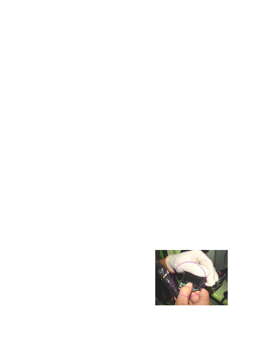
1.1.6. Disassemble the two connectors of the instrument harness and
the front compartment harness, as shown in the right figures: