Chery QQ6 (S21) / S12LHD. Manual - part 86
 

  Index      Chery     Chery QQ6 (S21) / S12LHD - service repair manual


Search            


Content   ..  84  85  86  87   ..


Chery QQ6 (S21) / S12LHD. Manual - part 86


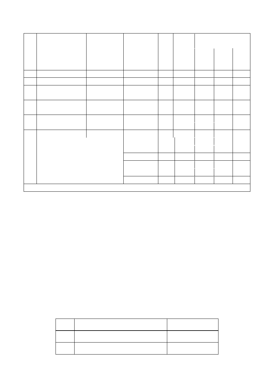
Multiple steps tightening (torque + 

angle) 

No. 

Connection part 

Part name 

Bolt 

(thread specification) 

Number 

of bolts/ 

gaskets 

(piece) 


Tightening 

torque 

Nm (primary 

tightening) 

First step 

tightening 

torque (Nm) 

Second step 

angle (°) 

Third step 

angle (°) 

64 

Exhaust manifold-cylinder head 

Stud bolt 

M8×1×46 

12+3 

—— 

—— 

—— 

65 

Exhaust manifold-cylinder head 

Hexagon nut 

M8 

20+5 

—— 

—— 

—— 

66 

Exhaust pipe thermal 

shield-exhaust pipe 

Hexagon bolt 

M8×12 

20+5 

—— 

—— 

—— 

67 

Oil return pipe bracket-cylinder 

block 

Hexagon bolt 

M8×20 

20+5 

—— 

—— 

—— 

68 

Oil return pipe hollow screw 


M14×1.5 

15+3 

—— 

—— 

—— 

69 

Bracket-oil-gas separator 

Inner hexagonal bolt 

M5×14 

6+2 

—— 

—— 

—— 

70 

Bracket-oil-gas separator 

Inner hexagonal bolt 

M6×14 

8+3 

—— 

—— 

—— 

M4 


2.5±0.5 

—— 

—— 

—— 

M5 


5±1.5 

—— 

—— 

—— 

M6 


8±3 

—— 

—— 

—— 

M7 


15±3 

—— 

—— 

—— 

M8 


20±5 

—— 

—— 

—— 

85 

Other 

M10 


40±5 

—— 

—— 

—— 


V.  The  Parts  where  Lubrication  are  Required  during  Assembly  of 

Engine 

No. 

Lubrication parts 

Type of lubricant 

Piston pin and pin hole 

SJ10W-40 

Piston ring groove 

SJ10W-40 

Connecting rod bearing shell and connecting 

rod journal 

SJ10W-40 

Cylinder sleeve hole 

SJ10W-40 

Main bearing lining and crankshaft main 

journal 

SJ10W-40 

Crankshaft thrust sheet (at oil groove side) 

and thrust surface 

SJ10W-40 

Head and thread of connecting rod bolt 

SJ10W-40 

Head and root of main bearing cap bolt 

SJ10W-40 

Rear oil seal edge and crankshaft oil seal 

journal 

SJ10W-40 

10 

Head and root of cylinder head bolt 

SJ10W-40 

11 

Valve guide orifice 

SJ10W-40 

12 

Valve stem 

SJ10W-40 

13 

Valve oil seal lip 

SJ10W-40 

14 

Valve seat insert 

SJ10W-40 

15 

Valve keeper ring groove 

SJ10W-40 

16 

Cam and journal of camshaft 

SJ10W-40 

17 

Camshaft bearing hole 

SJ10W-40 

18 

External surface and base plane of hydraulic 

jib 

SJ10W-40 

19 

Hydraulic jib hole and valve rocker arm head 

SJ10W-40 

20 

Outer ring of oil pump 

SJ10W-40 

21 

Edge or journal of camshaft oil seal 

SJ10W-40 

22 

Intake and exhaust phaser control valve 

gaskets 

SJ10W-40 

23 

Journal of intake and exhaust phaser 

SJ10W-40 


VI. The Parts where Rubber Coating are Required during Assembly 

of Engine 

No. 

Parts where rubber coating are required 


Type of sealant 

Cylinder block bowl plug 

Loctite 648 

Cylinder block main oil passage plug 

Loctite 243 

Junction plane of framework and cylinder 

block 

Loctite 515 

Outer ring of crankshaft rear oil seal 

Loctite 243 

Framework and oil pan 

Loctite 5910 

Cylinder head bowl plug 

Loctite 648 

Main oil passage screw plug 

Loctite 243 

Base plane of first bearing cap 

Loctite 574 

Water temperature sensor 

Loctite 243 

10 

Oil pressure switch 

Loctite 243 

11 

Flywheel bolt 

Loctite 243 

12 

Oil pan main oil passage plug 

Loctite 243 

13 

Engine oil collector separator bolt 

Loctite 243 


Chapter Three Special Tools 


I. Connotation of Special Tool Number 

In  order  to  know  or  find  the  tool  clearly  according  to  parts  number  and  improve  maintenance 

efficiency, special tools numbering is stipulated as follows:   

          □□□□□        ○        ○    ○    ○          □                                                                                                                                               


□ indicates a letter  ○ indicates an Arabic numeral 

Nomenclature  of  the  tool:  for  a  standard  part,  please  use  the  brand  and  model  recommended  by 

Chery company as reference. For example, CH indicates a non standard part, which means it is a 

special tool for repair of this part verified by After Sales Service Department of Chery Automobile 

Sales Co., Ltd. HAZET indicates a standard tool produced by this company. 

Connotation of system code corresponding to the tool:  

Number 

Position


1


Chassis 

2


Engine 

3


Transmission 

4


Accessory 

5


Body 

Corresponding series number of tools: from 001 to 999. 

Times of modifications of the tool: 

Number 

Modification


A


First modification 

Second modification 

Third modification 

Fourth modification 

Note: In alphabetical order. Bigger SN means more modification times.   

For example: CH-1002A means it is the 2# special tool for repair of chassis system that has been 

verified  by  After  Sales  Service  Department  of  Chery  Automobile  Sales  Co.,  Ltd.,  who  commits 

Please use the special tools that we designated to perform maintenance, otherwise it 

will cause accident or damage the machine. 

Maintemance times coresponding to tools   

SN coresponding to tools   

System code coresponding to tools   

Tools name 


Content   ..  84  85  86  87   ..