Chery Fora (Elara A520). Manual - part 192
Power Rear View Mirror System
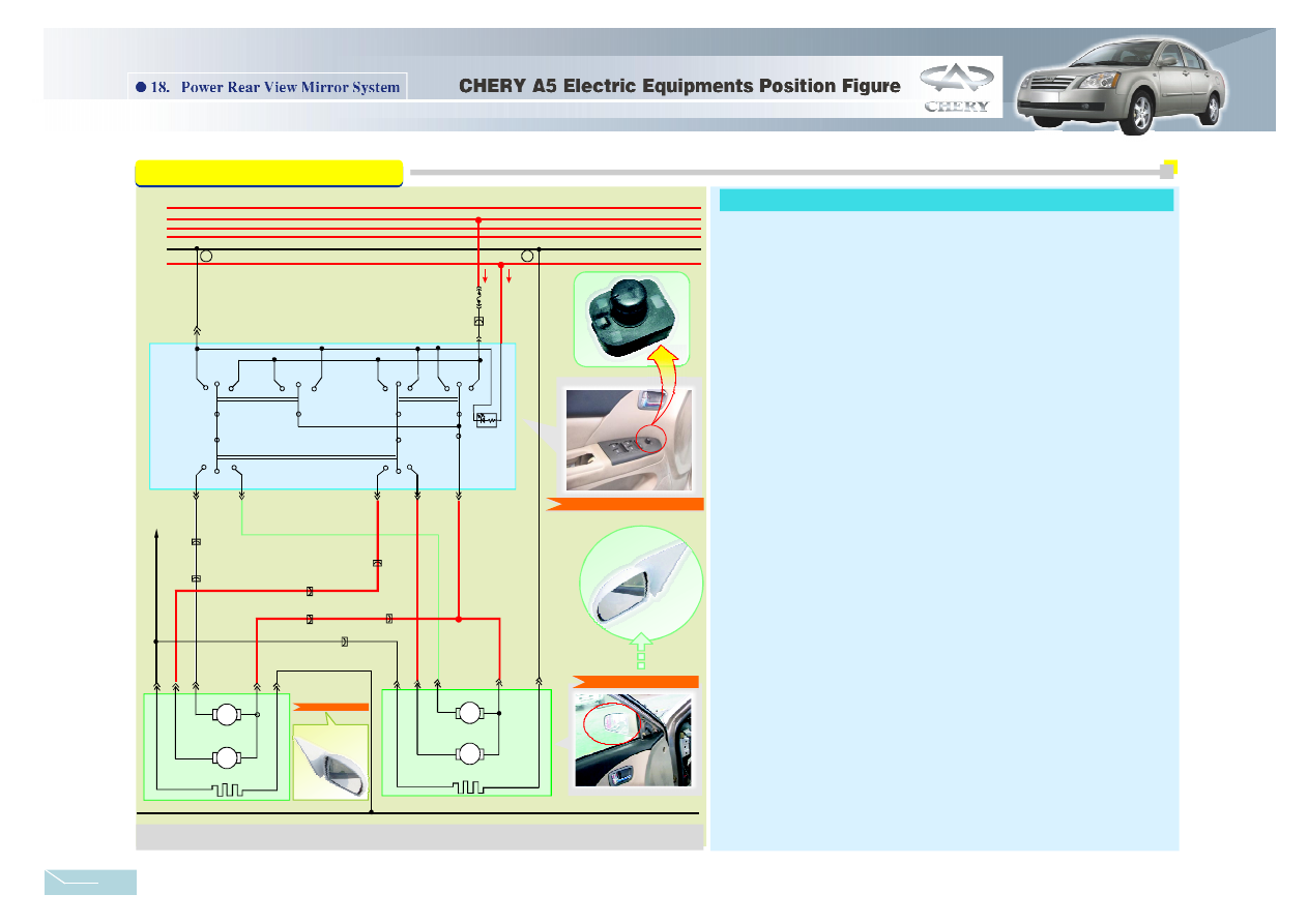
The power rear view mirror is shown as figure 18-1. When the ignition switch is set to the
position of ON or ST, the voltage of the battery gets to the 15th wire→7.5A fuse Fb2→7th pin of
power rear view mirror switch, the power rear view mirror get voltage.
→
→
→
→
→
→
→
→
→
→
→
→
→
→
→
→
→
→
→
→
choose the L button on the control switch panel, press
the UP key of the control switch, the 7th and 6th pin of rear view mirror switch are connectted,
the 3rd and 8th pin are connectted, the power go through the 7th pin of control switch
6th
pin rear left view up and down control motor 3rd pin of rear view mirror 8th pin ground.
The rear left view mirror will move upwards then.
press the DOWN key of the control switch, the 7th
and 3rd pin of rear view mirror switch are connectted, the 6th and 8th pin are connectted, the
power go through the 7th pin of control switch
3rd pin
rear left view up and down control
motor
6th pin of rear view mirror
8th pin
ground. The rear left view mirror will move
down-wards then.
press the LEFT key of the control switch, the 7th
and 6th pin of rear view mirror switch are connectted, the 2nd and 8th pin are connectted, the
power go through the 7th pin of rear view mirror 6th pin
rear left view left and right control
motor 2nd pin of rear view mirror
8th pin ground. The rear left view mirror will move left
then.
press the RIGHT key of the control switch, the
7th and 2nd pin of rear view mirror switch are connectted, the 6th and 8th pin are connectted,
the power go through the 7th pin of rear view mirror
2nd pin
rear left view left and right
control motor 6th pin of rear view mirror
8th pin ground. The rear left view mirror will
move right then.
The working principle of the right rear view mirror is the same with the left. Choose the R
button on the control switch panel, when press the UP button , the 7th and 6th pin of rear view
mirror switch are connectted, the 5th and 8th pin are connectted; when press the DOWN button,
the 7th and 5th pin of the rear view mirror are connectted, the 6th and 8th are connectted; when
press the LEFT button, the 7th and 6th pin of the rear view mirror are connectted, the 4th and
8th are connectted; when press the RIGHT button, the 7th and 4th pin of the rear view mirror
are connectted, the 6th and 8th are connectted.
1.The rear left view mirror incline to up and down, turn left and right circuit
(1)Rear left view mirror
(2)The rear right view mirror
2.Demist part circuit
Rear left view mirror upwards:
Rear left view mirror downwards:
Rear left view mirror move to left:
Rear left view mirror move to right:
There is demist circuit in the left and right power rear view mirror, when press the demist
switch, voltage from the ISU PP3 16# connect to 31st ground wire via rear left、 right view
mirror heating wire.
30
15
ACC1
ACC2
31
ILLUM
B
8
LEFT
9
+
-
LR
UD
-
+
M
-
+
+
-
LR
UD
-
+
+
-
+
+
-
-
4
2
W/B
LG
LH MRRDR
LEFT
RIG HT
DO WN
UP
RH MIRRDR
L H Mirror
DO WN
RIGHT
UP
5
3
6
R
R
R
FB2
7.5A
L19
7
0
1
9
M
M
M
RH MIRR DR
Power Rear V iew Mirror
Switch
To Front
ISU
PP3 16#
Front Ground/
Left 1/14
Front
Re ar Left
View
M irror
Front Ground/
Left 1/5
Front
Front Ground/
Right/14
Front
Front Grou nd/
Left 1 /3
Front
Fron t Ground/
Right/15
Front
Fr ont Ground/
Right /13
Fr ont
Front Ground /
Left 1/4
Front
Rear Left Vi ew Mirror
R ear Right
View
Mirro r
Re a r Right V iew Mi rror
Powe r Rear V iew M irror Switch
Figure18-1 Power Rear View Mirror Circuit Diagram
Power Rear View Mirror System Circuit analyse:
38