Chery Fora (Elara A520). Manual - part 189
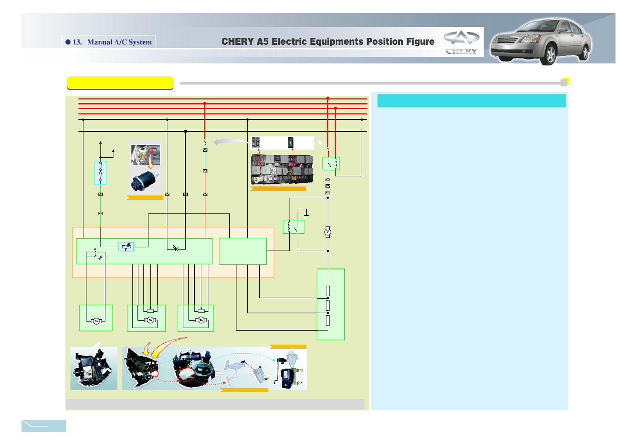
Manual A/C System Circuit Analyse:
The manual A/C is shown as figure13-1. When the ignition switch is at
the position of ON, the ACC1 and the 15th line get electricity.
The 15th line
power to the A20 pin of A/C controller .
lower peed djusting esistance
The two ends o f blower motor and h igh speed relay contact point (the
3rd、4th ) parallel connected, the high speed relay coil ( the 2nd p in)
connect to the B1 pi n of A/C c ontroller, when the high speed relay coil get
electricity, the conta ct
. The volta ge of the 3 0th line FB13 bl ower
relay coil
blower motor connect to ground. Then the blo wer motor will
run in high speed .
lower peed djusting e sistance
lower peed djusting
esistance
lower peed djust ing esistance
The A9、A12 pin of A/C controller
to the inner/o uter
circulation control motor, the control pa nel drive the circulation wind door
connecting bar、shi ft lever by controlling the inner/outer circulation servo
motor so as to drive the movement of the large、small wind door and realize
the control of inner/o uter circulation wind.
The A13、A14 pin of A/C controller
to the cool/warm
control mo tor, the c ontrol panel drive the conne cting bar、 shift lever of
temperature adjusting control mechani sm by controlling the blend door
servo moto r so as to drive the movement of the blend door and realize the
mixture of different ratio of air and gas.
The A18、 A1 9 pin of A/C controller
to the mode
control mo tor, the control panel drive the connecting bar、 shift lever of
wind direc tion adjusting control mechan ism by co ntrolling the mode wind
door servo motor, different shift lever control the open and cl ose of diffe rent
wind door and thereb y realize the control of air.
supplies
The ACC1 line supplies power to t he blower relay coil; the blower
relay coil g et electricity and the contact closed, the voltage of the 30th
line→FB13→blower relay contact point→blower motor→the 2nd pin of
b
s
a
r
.
closed
→
→
→
→
The 3 rd pin of t he b
s
a
r
is connectt ed to
the B4 pin of A/C controlle r, the 1st pin of b
s
a
r
is connec tted to the B2 pin of the A/C controller, the 4th pin of
b
s
a
r
are connectted to the B3 pin of the A/C
controller, the running speed of the blower motor is controlled by A/C
controller.
are connectted
are connectted
are connectted
connectted
Switch
The A3 pin o f A/C controller is
to the A/C Pressure
.
Figure13-1 Air Conditioning System Circuit Diagram
-
+
-
+
-
+
-
A9
A12
A14 A13 A6 A15 A2
A18 A19 A 4 A8 A1
A20
A 11
A10
A7
A3
A5
E4
E 2
D 1 D3 D6 D2 D5
C5
C2
C6
C3
C1
In tern al&external
Cir culation cont rol Mot or
Mode control Motor
Blowe r spe ed
adjusting r esistance
3
1
4
R3
R2
R1
2
B5
B 6
B1
B4
B2
B3
2
1
3
4
Blower
High
sp ee d
Rela y
Ground
+
B
Fuse bos /L/14#
IP1/A4
A/C 11
Blower
Relay
FB13
30A
FB7
5A
Fuse box /G/20#
R/L
A/C 4
B
W
T O ECU75#
TO ECU 60#
A/C
pres sure
Switch
A/C 7
Y/G
30
15
ACC1
ACC2
31
IL LU M
A/C S witch
A/C 6
Temperature Control
Motor
ECU /E
IP1/B6
A/C 12
R
Br
A/C press ure S witch
F7
A/C
15th line power fuse
A/C
Blower fuse
F 13
Front Eng ine Compartment Fuse Box
Mode Con trol Motor
Temperature Control Motor
Manual A/C System
2 6