Chery Fora (Elara A520). Manual - part 149
CHERY·A21 SERVICE MANUAL ENGINE EFI SYSTEM
35
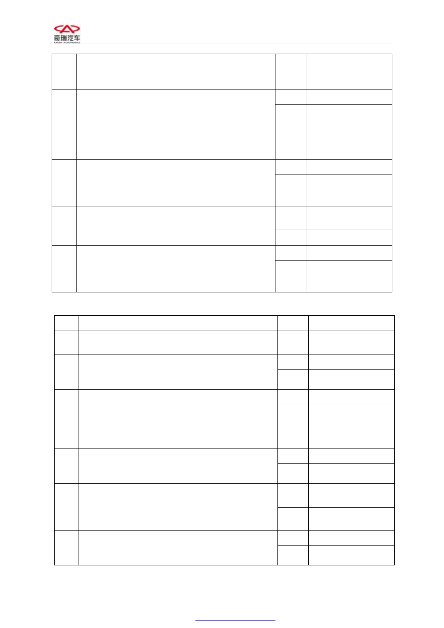
at that time).
Notice: if the value always is - 40
there is perhaps
℃
open circuit failure in the circuit.
Yes
Next step
3
Take off the joint of coolant temperature sensor on
the cable, check the resistance values using
multimeter between the sensor connector No. 1 and
the No. 2 and check if it is corresponding to its
temperature (please reference the related section of
this service manual).
No
Replace sensor
Yes
To step 6
4
Take off the joint of coolant temperature sensor on
the cable, check the voltage between pin No.1 and
pin No.2 by multimeter and observe if it is around
5V.
No
Next step
Yes
Repair or replace
cable
5
Check if it is short circuit to ground between ECU
pin No.39, No. 35 and sensor connector No.1, No.2.
No
Next step
Yes
Diagnosis help
6
Start the engine at idle speed. Observe the value
changes of diagnostic tester “coolant temperature”,
the value should increase with the increase of the
engine coolant temperature.
No
Replace sensor
DTC: P0122 Indicated temperature is much lower of the air intake temperature sensor.
No.
Operating steps
Result
Follow up steps
1
Connect the diagnostic tester and commutator, put
the ignition switch to “ON”.
Next step
Yes
Next step
2
Observe “throttle valve absolute opening” item in
data flow, check the value if it is between 4% and
10% (specific data is correlated to the vehicle type).
No
To step No. 5
Yes
Next step
3
Step on the accelerator slowly to complete opening
and observe “throttle valve absolute opening” item
in data flow, check if the value is increased to around
85-90% with the opening of the throttle valve
(specific data is correlated to the vehicle type).
No
To step No. 5
Yes
Replace the sensor
4
Repeat step 3 and observe “throttle valve absolute
opening” item in data flow, and check if there is
jump during the changes.
No
Next step
Yes
Repair or replace
cable
5
Take off the joint of throttle valve positioning sensor
on the cable, check if there is short circuit to ground
between pin No.17, No.32, No.16 of ECU and pin
No.1, No.2, No.3.
No
Next step
Yes
Replace sensor
6
Check the voltage between pin No.1 and pin No.2 by
multimeter and observe if it is around 5V.
No
Diagnosis help