Chery Fora (Elara A520). Manual - part 140
 

  Index      Chery     Chery Fora (Elara A520) - service repair manual


Search            


Content   ..  138  139  140  141   ..


Chery Fora (Elara A520). Manual - part 140


52 

 
7.3  Check 

1) 

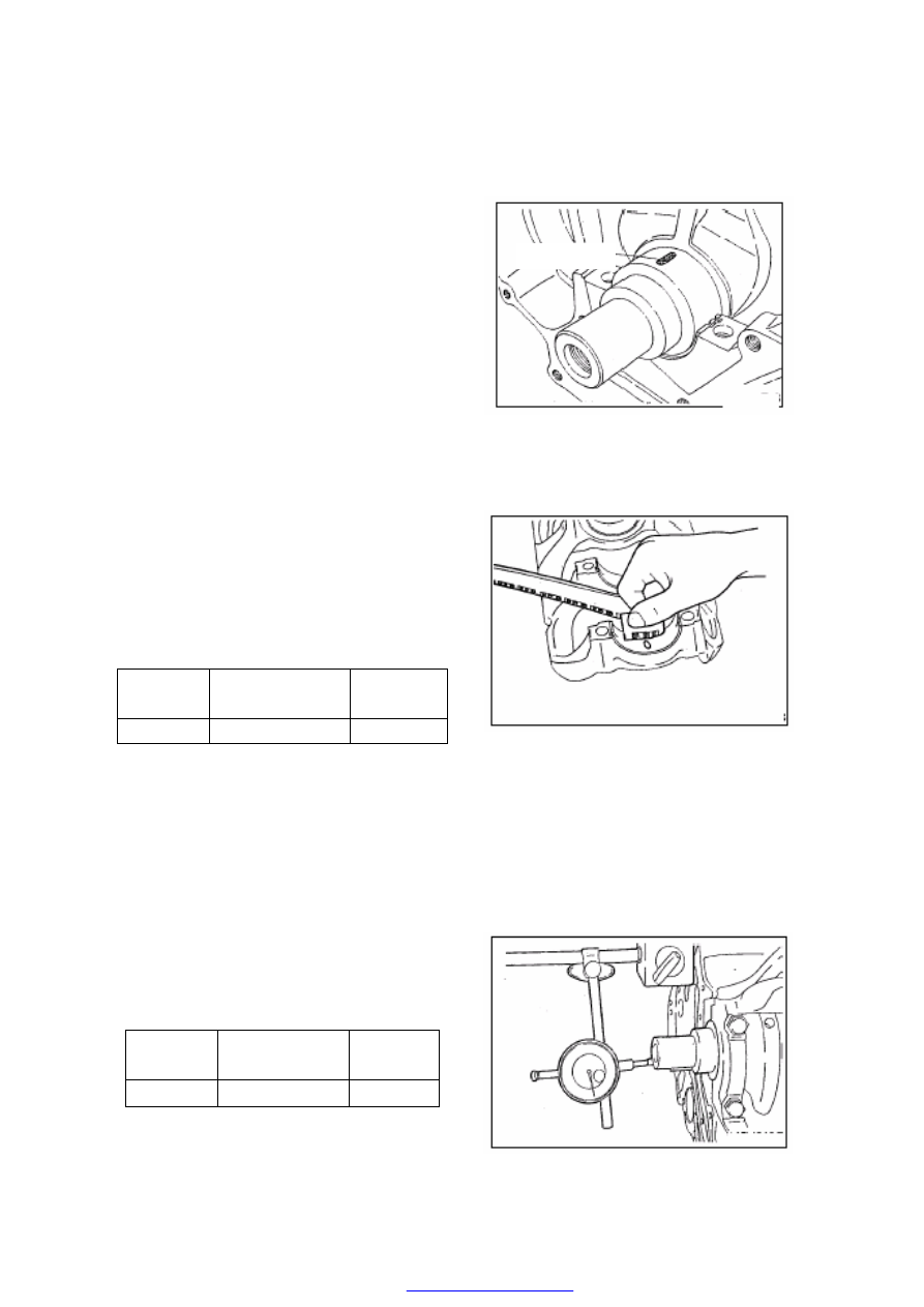
Check  the  oil  clearance  of  crankshaft 
main journal. 

a) 

Clean the journal and bearing bushing. 

b) 

Installation of crankshaft 

c) 

Cut the plastic gauge to make it have the 
same length with that of the bearing, and 
then put it onto the crankshaft journal to 
make  it  parallel  with  the  central  line  of 
shaft. 


d) 

Install  the  master  bearing  cap  carefully, 
and fasten the bolts to specified torque.   

e) 

Dismantle  the  master  bearing  cap 
carefully. 

f) 

Use the measuring rule on the packaging 
bag  of  plastic  gauge  to  measure  the 
width  of  the  widest  portion  of  flattened 
plastic wire, and get the clearance value. 


Standard value 

Limit 
value 

Clearance 

0.022 

0.058 

If the clearance value exceeds the limit value, 
please replace the bearing bushing. 

Note:  When  replacing  the  bearing  bushing, 
you  must replace the whole group of  bearing 
bushings. 


2) 

Measure 

the 

axial 

clearance 

of 

crankshaft 

After 

mounting 

the 

crankshaft,  you  can  use  micrometer 
guage to measure the axial clearance. 


Standard value 

Limit 

value 

Clearance 

0.07 

0.265 

If the measured value exceeds the limit value, 
please replace the thrust washer. 


Plastic Gauge 


53 

 
7.4  Installation 

1) 

Clean  up  the  short  engine,  and  apply 
engine lubricant. 

2) 

Install  the  crankshaft  correctly,  and 
mount  the  thrust  washer  in  proper 
position. 

3) 

Latch  on  the  cylinder  block  frame,  and 
fasten the crankshaft fixed bolts.   

The  fastening  sequence  is  illustrated  in  the 
figure. 

Torque: 

4) 

Mount  the  bolts  onto  the  frame 
periphery, and fasten them. 

Torque: 

5) 

Mount  oil  strainer,  oil  pan,  front  and 
rear oil seals of crankshaft and oil pump. 

6) 

Mount  engine  accessories,  lift  and 
install  the  engine  onto  the  car,  mount 
water  pipe,  and  insert  all  electrical 
plugs.   


CHERY·A21 SERVICE MANUAL                                  ENGINE EFI SYSTEM 

CONTENT 

1. NOTICE TO THE EFI SYSTEM SERVICE .........................................................................................3 

1.1. GENERAL SERVICE ...........................................................................................................................3 

1.2. NOTICE DURING THE SERVICE.............................................................................................3 

1.3. SERVICE TOOLS .........................................................................................................................4 

1.4. EXPLANATIONS OF THE ABBREVIATION IN THE MANUAL.........................................6 

2. ME7.9.7 SYSTEM INTRODUCTION....................................................................................................6 

2.1. SYSTEM BASIC PRINCIPLE.....................................................................................................6 

2.1.1 SYSTEM GENERAL INTRODUCTION: ME7.9.7-MOTRONIC EMS .......................6 

2.2. CONTROL SIGNAL: ME7.9.7 SYSTEM INPUT/OUTPUT SIGNAL....................................8 

2.3. INTRODUCTION OF SYSTEM MALFUNCTION DIAGNOSIS FUNCTION.....................9 

2.3.1. MALFUNCTION INFORMATION RECORD ...............................................................9 

2.3.2, CONTROL STRATEGY OF FAILURE LAMP ..............................................................9 

2.3.3, DIAGNOSIS METER CONNECTION..........................................................................10 

2.3.4, READ MALFUNCTION INFORMATION BY WINK CODE....................................10 

3. WORKING PRINCIPLE AND CHARACTER OF EFI SYSTEM ELEMENT...............................10 

3.1 ELECTRONIC CONTROL UNIT - ECU..................................................................................10 

3.2 COOLANT TEMPERATURE SENSOR....................................................................................14 

3.3 KNOCK SENSOR ........................................................................................................................15 

3.4 OXYGEN SENSOR......................................................................................................................16 

3.5 SPEED SENSOR (CRANKCASE POSITIONING SENSOR).................................................17 

3.6 PHASE SENSOR (CAM SHAFT POSITIONING SENSOR) ..................................................19 

3.7 ELECTRIC FUEL PUMP ...........................................................................................................20 

3.8 ELECTROMAGNETIC INJECTOR.........................................................................................21 

3.9 AIR FLOW SENSOR ...................................................................................................................22 

3.10 DOUBLE SPARK IGNITION COIL........................................................................................23 

3.11 CARBON CANISTER SOLENOID VALVE............................................................................25 

3.12 FUEL PRESSURE REGULATOR............................................................................................26 

3.13 ELECTRONIC THROTTLE VALVE AND ACCELERATOR..............................................27 

3.14 FAN CONTROL .........................................................................................................................28 

3.15 AIR CONDITIONER CONTROL............................................................................................29 

4 ME7 SYSTEM TEST AND REPAIR ACCORDING TO TDC ...........................................................30 

4.1 ENGINE DTC (DIAGNOSTIC TROUBLE CODE) LIST.......................................................30 

4.2 DIAGNOSIS FLOW WHEN THERE IS DIFFERENT DTC ..................................................32 

5. TYPICAL FAILURE AND ITS DIAGNOSIS FLOW.........................................................................52 

5.1 EXPLANATION ...........................................................................................................................52 

5.2 TYPICAL FAILURE DIAGNOSIS FLOW ...............................................................................53 

1. The engine does not rotate or rotate slowly when it is started ............................................53 

2. The engine can draw rotating but can not start successfully when it is started. ...............54 

3. It is hard to start the heating car. ..........................................................................................55 

4. It’s hard to start the cold car..................................................................................................56 

5. Normal engine speed but hard to start at any time. ............................................................57 

6. Regular starts but the idle speed is not steady at any time. ................................................58 

7. Regular starts but the idle speed is not steady during engine heating. ..............................59 

CHERY·A21 SERVICE MANUAL                                  ENGINE EFI SYSTEM 

8. Regular starts but idle speed is not steady after the engine heating...................................60 

9. Regular starts but idle speed is not steady or dying out when there is partial loading. ...61 

10. Regular starts with high idle speed. ....................................................................................62 

11. Low engine speed or dying out exists when it is accelerated. ............................................63 

12. React slowly when it is accelerated......................................................................................64 

13. The performance is poor when it is accelerated. ................................................................65 


Content   ..  138  139  140  141   ..