Chery Fora (Elara A520). Manual - part 133
 

  Index      Chery     Chery Fora (Elara A520) - service repair manual


Search            


Content   ..  131  132  133  134   ..


Chery Fora (Elara A520). Manual - part 133


24 


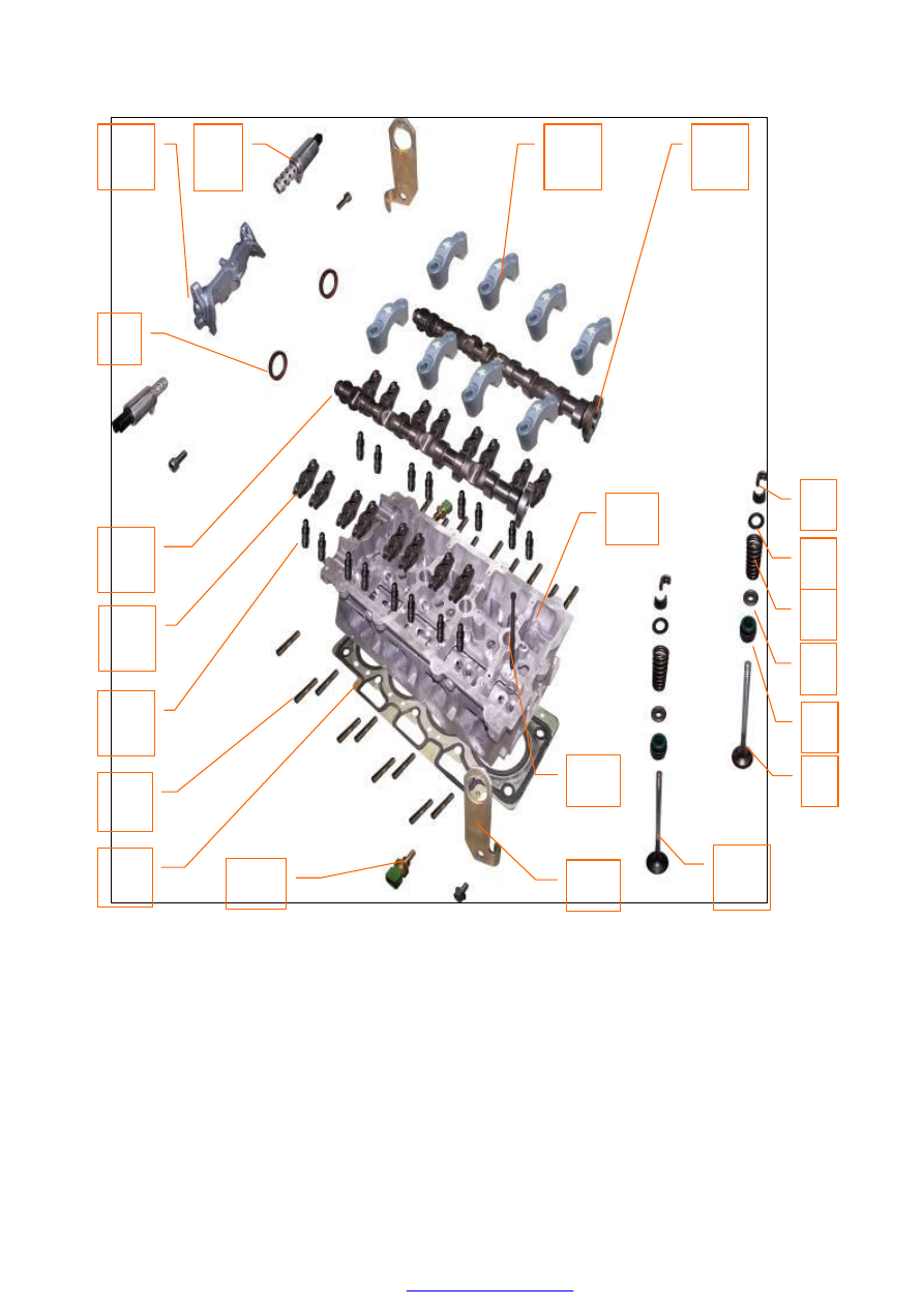
1. Intake Valve   
2. Valve Oil Seal 
3. Spring Seat 
4. Valve Spring 
5. Spring Retainer 
6. Keeper   
7. Exhaust Valve 
8. Intake Camshaft Assembly 
9. Bearing Cap Assembly   
10. Control Valve-Camshaft Phaser Assembly 
11. First Bearing Cap Assembly 

12. Front Camshaft Oil Seal 
13. Exhaust Camshaft Assembly 
14. Rocker Assembly 
15. Hydraulic Tappet Assembly 
16. Stud Bolt (9 Bars) 
17. Cylinder Head Gasket   
18. Temperature Sensor 
19. Engine Hanger 
20. Cylinder head Bolt 
21. CBR Cylinder head Assembly 

11 

15 

14 

13 

10 

17 

18 

12 

16 

19 

20 

21 


25 


2. Maintenance 

2.1


Replace  intake  manifold,  CBR  control 
valve plate, delivery pipe, oil injector 

2.1.1


Needed tools and auxiliary materials   

Ratchet  wheel,  ratchet  rod,  10#  sleeve  and 
crosshead screwdriver 

2.1.2


Process of removal 

1)


Put the ignition key at the OFF position. 

2)


Loosen the oil injector plug.


3)


Loosen the electric plug of CBR control 
valve, 

and 

dismantle 

the 

bolts 

connecting  the  engine  oil  dipstick  and 
intake manifold.   


4)


Loosen the  clamp  at the  connection  end 
of air intake hose and valve body. 


5)


Dismantle  the  connecting  bolts  of valve 
body, and take out the valve body.   


6)


Loosen the joint of oil intake pipe.


7)


Dismantle  the  fixed  nut  of  intake 
manifold,  and  remove  the  intake 
manifold. 


26 


2.1.3


Installation steps 

The  installing  steps  are  reverse  to  those  for 
removal. 

Note:  Pay  more  attention  to  the  position  of 
seal ring. There is a slot at the arrow pointing 
position. 


2.2


Replace  camshaft,  bearing  bushing, 
valve and valve oil seal 

2.2.1


Needed tools and auxiliary materials   

Special  tool  for  valve  oil  seal,  engine 
lubricant,  a  set  of  sleeve  tools  and  one 
adjustable  wrench,  special  timing  tool,  a  set 
of allen wrenches. 

2.2.2


Removal 

1)


Dismantle  the  dynamo  belt  (detailed 
methods  are  shown  in  the  “removal  of 
dynamo belt ”). 

2)


Dismantle  the  timing  belt  (detailed 
method  are  shown  in  the  “  replacement 
of  engine  timing  belt  and  timing 
calibration”.   

3)


Dismantle  the  engine  valve  chamber 
cover. 


4) 

Clamp  the  engine  timing  special  tool, 
the camshaft tool  into the camshaft slot, 
and use bolts to fix it. 


Camshaft Tool 


27 


5) 

Use  torque  wrench  to  remove  the  air 
intake and exhaust camshaft pulleys.   


6) 

Dismantle the back cover of timing belt. 


7) 

Dismantle  the  air  intake  and  exhaust 
camshaft bearing caps in turn, and place 
them well in order. 

Note:  The  second,  third,  fourth  and  fifth 
camshaft bearing caps are marked with I1, I2, 
I3, I4  (E1,  E2,  E3, E4),  which  stands  for the 
corresponding  bearing  cap  of  1,  2,  3,  4 
cylinder respectively. 

8) 

Take  out  the  camshaft  and  hydraulic 
tappet.   

9) 

Dismantle  the  valve  spring.  Use  special 
tool to dismantle the valve spring. 

10)  Use  special  valve  oil  seal  tool  to 

dismantle the old valve oil seal.


Content   ..  131  132  133  134   ..