Chery Fora (Elara A520). Manual - part 38
 

  Index      Chery     Chery Fora (Elara A520) - service repair manual


Search            


Content   ..  36  37  38  39   ..


Chery Fora (Elara A520). Manual - part 38


11 

 
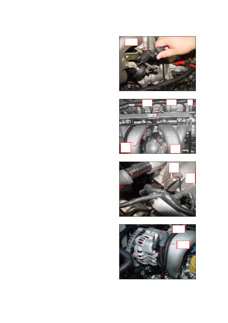
5.  Remove  the  (f)  the  harness  plug  of  CBR 

solenoid valve. 


6.  Dismantle  (g)  the  earth  cable  bolt  of 

cylinder  head,  remove  (h)  the  wire 
harness  plug  of  starter  coil,  (i)  wire 
harness  plugs  of  four  oil  injectors,  (j) 
knock  sensor  plug,  (k)  wire  harness  plug 
of throttle valve controller. 


7.  Remove  (l.)  CBR  solenoid  valve  plugs, 

and (m) oil temperature sensor plugs 


8.  Loosen (n) generator positive pole output, 

pull out (o) exciting current harness plugs 
as  well  as  the  plugs  of  relevant  parts  of 
the  A/C  compressor,  steering  booster 
pump,  oxygen  sensor,  and  A/C  high-low 
voltage  switch..  Loosen  the  fixed  bolt  of 
starter harness to confirm the plugs of all 
parts are completely separated. 


12 


9.  Dismantle  (p)  transmission  gearshift 

cable and (q) hydraulic pipe of clutch. 


10.  Use  crane  to  hoist  the  engine  hanger 

from  the  top,  and  dismantle  the  two 
hexagonal 

flange 

bolts 

of 

front 

suspension bracket. 


11.  Dismantle  the  hexagonal  flange  bolts  of 

girder under the car body. 


12.  Remove  the  hexagonal  flange  bolts  of 

rear  suspension-cushion  assembly  of   
engine. 


13 


13.


Dismantle  the  coolant  reservoir  and 
cleaning the reservoir.   


14.


Loosen the  three  hexagonal  flange  bolts 
of engine's right bracket. 


15.


Loosen  the  three  bolts  of  right 
suspension  cushion,  and  dismantle  the 
right  suspension  cushion  assembly  and 
bracket.   


16.


Dismantle  the  hexagonal  flange  bolts  of 
left  suspension  cushion  in  order  to 
ensure  no  connection  between  the 
engine  and  car  body.  Lift  down  the 
crane  carefully  and  shift  out  the  power 
assembly. 


14 

SECTION III ENGINE ACCESSORIES 

1 Replacement of Dynamo belt 

1.1  Needed  tools  and  auxiliary  materials 13 

#open end wrench and new dynamo belt 

1.2  Process of removal 

As  the  figure  illustrated,  rotate  the13#open 
end  wrench  counterclockwise  and  recede the 
tension  pulley.  At  the  same  time,  the  belt 
tension shall disappear, so you can dismantle 
the belt. 

1.3  Installation steps 

The  installing  steps  are  reverse  to  those  for 
removal. 


2 Replacement of Generator Assembly 

2.1  Needed  tools  and  auxiliary  materials 

Allen wrench, ratchet wheel, 13# sleeve, 
10# open end wrench. 

2.2  Process of removal: 

1) 

Dismantle  the  negative  pole  harness  of 
battery.   

2) 

Dismantle  the  bolts  connecting  the 
generator  and  harness,  and  take  out  the 
harness. 


3) 

Pull  out  the  harness  plugs  of  generator 
regulator. 


Content   ..  36  37  38  39   ..