Chery Fora (Elara A520). Manual - part 32
 

  Index      Chery     Chery Fora (Elara A520) - service repair manual


Search            


Content   ..  30  31  32  33   ..


Chery Fora (Elara A520). Manual - part 32


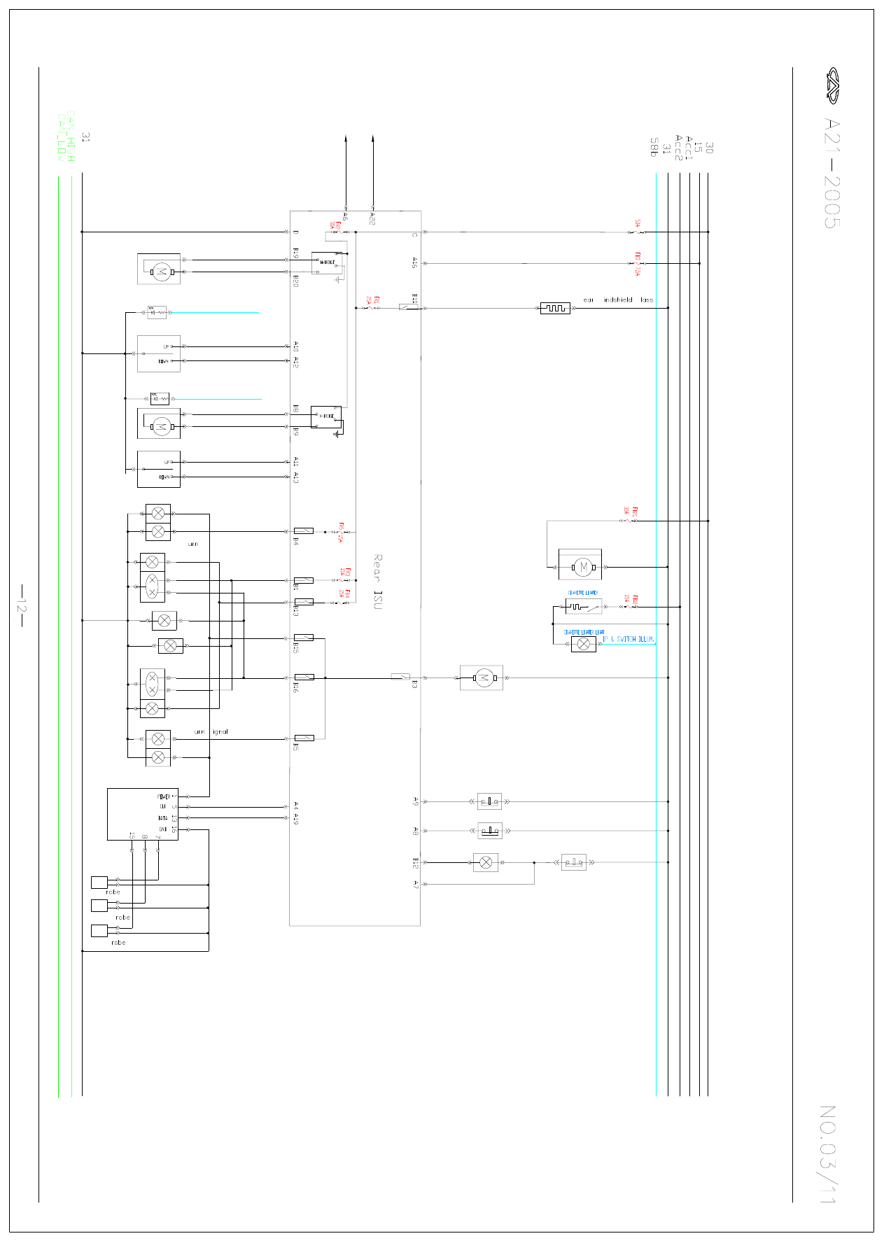
RE
A

R

 ISU 

SYSTE

M

C

IR
C

UIT

 D
IA

G

RA

M

Rad

ar

 M
o

du
le

T

o F
ro

n

t ISU A29

T

ru

nk Lamp

T

runk Swit

ch

Contact Switch of Left Rear Door

Regulator Switch of Right Rear Door 

Regulator Switch of Left Rear Door

T

o F
ro

n

t ISU A30

High Mounted Stop Lamp

T

runk L

ock 

Ac
tua
tor

Left T

Light

Regulator Motor of Right Rear Door

R

W

G

 Heater resistor

Left Backup Lamp

License Lamp

Left Position Lamp

Left Rear Regulator Motor

Left P

Contact Switch of Right Rear Door

Right Position Lamp

Right Rear Fog Lamp

Right T

S

 Lamp

Right Backup Lamp

Middle P

Right P

Generated by Foxit PDF Creator © Foxit Software

http://www.foxitsoftware.com   For evaluation only.

CONTENT

 1. READING INSTRUCTIONS..............................01

2. START AND CHARGE SYSTEM......................02

3. ABS SYSTEM.....................................................03

4. AIR CONDITIONING  SYSTEM......................04

5. AUDIO SYSTEM................................................05

6. AIR BAG SYSTEM.............................................06

7. INSTRUMENT SYSTEM...................................07

8. ENGINE SYSTEM..............................................08

9. FRONT ISU SYSTEM........................................09

10. FRONT ISU SYSTEM......................................10

11. REAR ISU SYSTEM.........................................11

CIRCUIT DIAGRAM

12. FUSES................................................................12

CIRCUIT DIAGRAM

READING INSTRUCTIONS

2. This circuit diagram is suitable to configuration of A21 1.6 and 2.0. 

Considering the time limit, it is liable to mistakes or omissions. Please 

contact with Service Technology Dep. of sales company if any 

unconformity is found.

  TEL 0553-5922392

  FAX 0553-5840795


1. NO. of relay circuit:

   30 Coming from storage battery

   15 Controling by ignition switch
   ACC Ignition switch radio set 

   31 Ground

   58b Luminous regulating line


Terminal

START

LOCK

Position

ON

ACC

ST2

ACC

AM2

IG2

AM1

START AND CHARGE SYSTEM

CIRCUIT DIAGRAM

Starter Relay

Ignition Switch

Generator

Starter

Storage 

Battery

To instrument 16#

75Ah


Content   ..  30  31  32  33   ..