Chery B11. Manual - part 228
Chery·Maintenance Manual for Oriental Son
Automatic Transmission
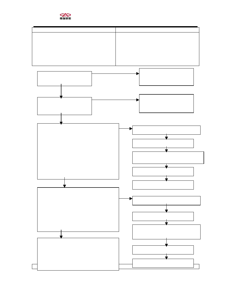
the reverse gear
If the transmission ratio of the reverse gear
be
ird gear as a protection.
Input shaft speed sensor fault
d sensor fault
guard ring fault
ive gear or driven gear fault
Low/ reverse gear braking system fault
Reverse-gear clutch system fault
Noise interference
does not conform to the input of input shaft
speed sensor and the output of output shaft
speed sensor is increased, then Code 46 will
output. If Code 46 is output for 4 times
running, then the gearbox will be locked at the
Output shaft spee
Deceleration clutch
Transfer case dr
th
Code 51 Abnormal communications with
Possible cause
MUT-Ⅱ S-slfDiag code
Is Troubleshooting Code 22
output?
MUT-Ⅱ S-slfDiag code
Is Troubleshooting Code
23 output?
Measure the output wave form of input shaft
e
.
speed sensor with an oscilloscope
Connect with connector B-71 and measure th
voltage between A/T-ECU 31 and 43
Engine: 2,000rpm (about 50km/h)
Gearbox: third gear
Normal: e.g. one kind of wave form on Page
23-42 (using the checking sequence of the
oscilloscope) is output (fluctuate between 0 and
5V) a
wave
nd there is no noise interference for the
form.
Measure the output wave form of output shaft
speed sensor
ure th
Connect with connector B-68 and meas
voltage between A/T-ECU 32 and 43.
e
x: third gear
Gearbo
Normal: e.g. one kind of wave form on Page
23-42 (using the checking sequence of the
oscilloscope) is output (fluctuate between 0 and
5V) and there is no noise interference for the
wave form.
A/T overhaul
Check deceleration clutch system (Code 41 is
output or no troubleshooting code is output)
Check reverse-gear clutch system (No code is
output)
Check input shaft speed
sensor system (refer to
Yes
Page 23-14)
Check input shaft speed
sensor system (refer to
Page 23-15)
No
Replace input shaft speed sensor
Check fault sym toms
p
A/T overhaul: replace deceleration
clutch guard ring
Check fault sym toms
p
Eliminate noise interference
Replace
tp
ft speed
ou ut sha
sensor
Check fault symptoms
A/T overhaul: replace transfer
case drive gear and driven gear
Check fault sym toms
p
Eliminate noise interference
Yes
No
Abnormal
Normal
Abnormal
Normal
Abnormal
a
Abnormal
Abnormal
Abnorm l
80