Chery B11. Manual - part 57


  Index      Chery     Chery B11 - service repair manual


Search            


Content   ..  55  56  57  58   ..


Chery B11. Manual - part 57


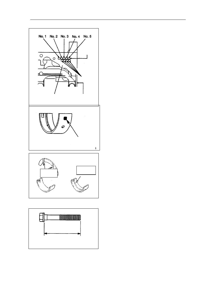
Examples for bearings choosing   


 If identification color of 

crankshaft main journal is 
yellow and identification mark 
of spindle bore is “1”, choose 

the No. 1,2,4,5 bearing of which 
identification mark is “2” and 
identification color is “yellow” and 
No.3 bearing of which identification 
mark is “1” and identification color 
is “green”. 

Main bearing bore size

identification mark 

Main  bearing

bore 

identification 

mark 


If there’s no identification paint 

color on crankshaft, measure main 
journal and choose corresponding 
groups of bearing according to 
measurement value. 


Cylinder 

inner 

diameter size

mark 

Rear face of
cylinder body 

Cylinder 
block bottom 


Crankshaft bearing size identification
mark or color 

(2)  Install bearing with grooves on one 

side of cylinder block. 

(3)  Install bearing without grooves on 

one side of main bearing cap.   

Identification mark or
color 

(4) Install two of thrust bearing of 

crankshaft in No. 3 main bearing 
hole of cylinder block. For 
convenient installation, apply a little 
oil on the surface of thrust bearing. 

(5) One side of thrust bearing with 

groove should face towards 
crankshaft crank arm. 


oil ditch

oil ditch 


Main bearing cap and main bearing cap 
bolt installation 
(1)  Install arrowhead of main bearing 

cap towards the side of timing belt. 

 
(2)  Before screwing main bearing cap 

bolt on, assure that length of bolts is 
less than value limit. If not, replace 
the bolt. 
Limit value (A):71.1mm 


(3)  Daub oil on screw thread of nuts and 

seat surface. 

(4) Screw main bearing cap bolt on by 

torque of 25N.M,  according  to 
regulated order. 


(5)  Daub paint mark on every nut head. 

(6) Daub paint mark on the main 

bearing cap of which the position is 

from paint mark on bolts to 

screwing direction of 90~100°   

(7)  Screw nuts on from 90 ~ 100 °

regulated in the picture above, 

according to screwing order till paint 

mark on bolts aligns paint mark on 

main bearing cap. 
 

Notice: 

Arrow  

Paint mark 

Paint mark


If screwing angle is less than 90°

screwing specified capability can’t 

be assured. When screwing it on, 

pay much attention to screwing 

angle. 


If screwing nuts are excessively  

tightened (exceed angle of 100°) , 

screw nuts off totally. And restart 

to screw nuts from Step 1.   


(8)  After installing main bearing cap, 

assure if crankshaft can turn 

smoothly and check axial clearance. 

If axial clearance exceeds usage 

limit value, replace NO.3 crankshaft 

thrust bearing of crankshaft. 

Standard value:0.05~0.18mm 

Limit value:0.25mm 


  Oil seal installation 

Rear oil seal cap installation 
Specified sealant: 
Brand : Mitsubishi pure components 
MD970389 or corresponding 

equivalents. 


 Notices: 

(1)  Ensure rear oil seal cap is installed 

quickly when sealant is still wet. 

( ≤15 min)   

(2) After  installing,  keep  sealed 

area away from lubricate grease 

and coolant for one hour. 


Maintenance Manual for Chery·Oriental Son                     

Engine Section


Chapter 5 Lubrication System 

Front cover, oil pump, balance axle and 

oil pan 


Disassembling Steps 
1.Oil cleaner 
2.Oil drain plug 
3.Oil drain plug cushion 
4.Oil pan 
5. Oil collect filter 
6. Oil collect filter cushion 
7. Plug 
8. O-shape ring 
9. Flange bolt 
10. Oil pressure switch 
11. Pressure relief plug 
12. Seal cushion 
13. Pressure relief spring 
14. Pressure-relief plunger 


Daub oil on all internal

components when

assembling 

Disassembling 
illustration 


15. Oil cleaner bracket 
16. Oil cleaner bracket cushion 
17. Oil pump cover 
18. Oil pump driven gear 
19. Oil pump drive gear 
20. Crankshaft front oil seal 
21. Oil pump oil seal 
22. Balance axle oil seal 
23. Front cover 
24. Front cover cushion 
25. Left balance axle 
26. Right balance axle 
27. Right balance axle front bearing 
28. Left balance axle bearing 
29. Right balance axle rear bearing 


Maintenance Manual for Chery·Oriental Son                     

Engine Section


Disassemble Notice 

MD998727 

Oil pan disassemble 

(1)  Disassemble all oil pan bolts 

(2)  Insert special tool between cylinder body and 

oil pan. 

Remarks: 

Do not use screwdriver or chisel instead of 

special tool, otherwise the edge of oil pan 

may be distorted and oil leakage will occur. 


MD998162

Plug disassemble 

Disassemble plug cock with special tool. If 

plug is tightened, tap the plug top with 

hammer several times and the plug will loose. 


Flange bolt disassemble 


(1)  Disassemble plug from cylinder body. 

(2) Insert cross screwdriver (pole diameter is 

8mm) into the plug hole and lock balance 

axle. 


(3)  Loosen flange bolt 


plug 

Screwdriver


Right balance axle front bearing disassemble 

(1)Disassemble balance axle right-front bearing 

with special tool from cylinder body. 

Remarks 


Front bearing must be disassembled firstly. If it is 

not disassembled, rear bearing puller can not be 

used. 

Front 

bearing

MD998371 


Content   ..  55  56  57  58   ..