Chery A18. Manual - part 32
 

  Index      Chery     Chery A18 - service repair manual


Search            


Content   ..  30  31  32  33   ..


Chery A18. Manual - part 32


Grinding valve and valve seat ring 


UAES’s new 

two-valve     

Face angle of intake valve 

44º30′---45º30′ 

Width of the sealing band 

for the intake valve seat 

ring 

1.75---2.32mm 

Face angle of exhaust 

valve 

91º (0º-0º30ˊ) 

Width of the sealing band 
for the exhaust valve seat 

ring 

1.44±0.1 


Installation 
Before  installation,  the  cylinder  head  shall  be 
completely  cleaned  and  there  shall  be  no any  trace 
of  abrasive  dust  on  the  cylinder  head,  valve  or 
valve guide.   

Lubricate the valve stem and valve guide bore with 
clean motor oil. 

Install the  valve.  The  assembly  shall  be  completed 
according to the original valve indicators. 

Note: The intake valves are interchangeable, but 

the exhaust valves are not. 


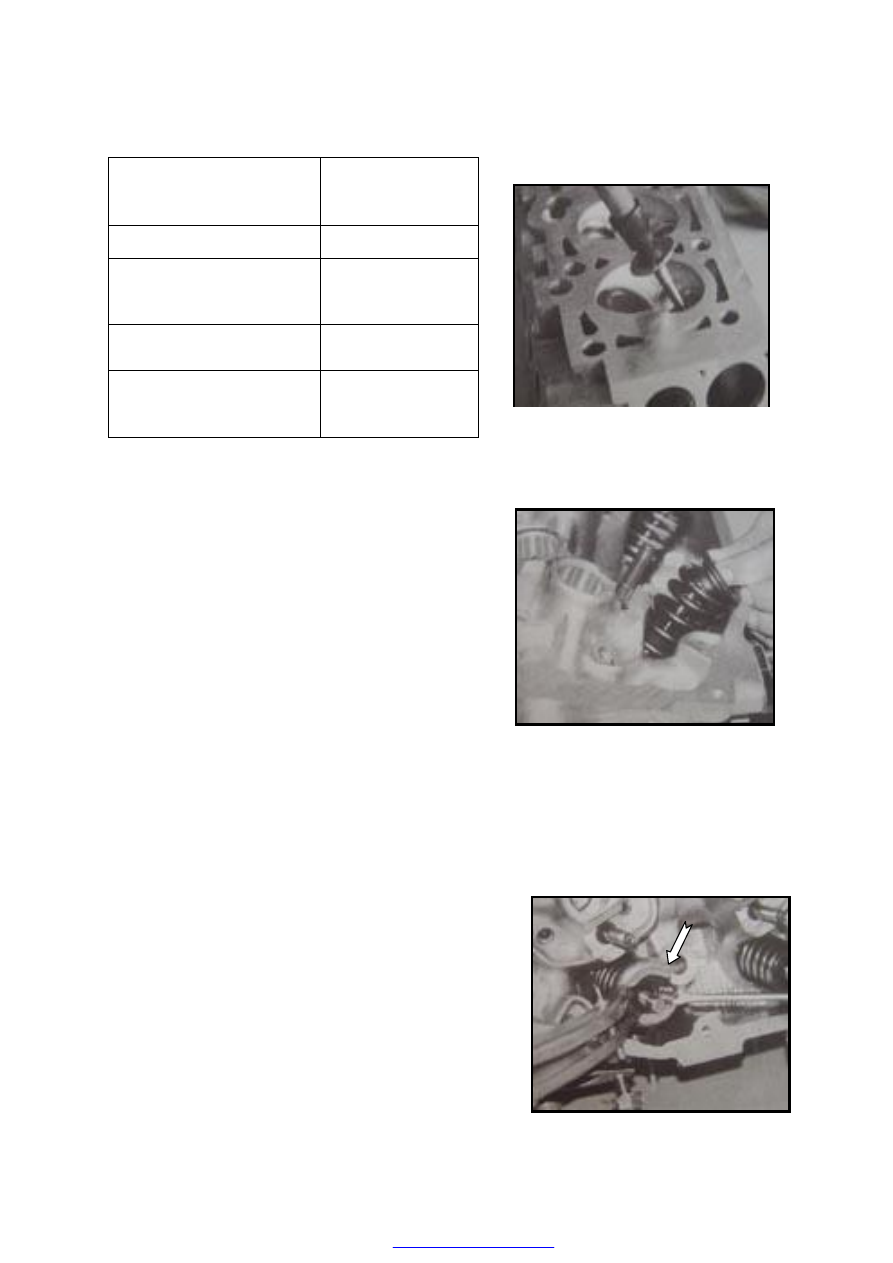
Press  the  valve  oil  seal  and  spring  seat  assembly 
into  the  upper  end  of  the  valve  guide,  apply  some 
motor  oil  on  the  guide  opening  or  the  edge  of  the 
valve oil seal and wrap the glove of the valve cotter 
by  adhesive  tape.  After  the  valve  is  installed,  take 
away the adhesive tape. 


Install  the  valve  spring  and  valve  spring  seat, 
compress  the  valve  spring  seat  to  the  stroke  that 
enables the valve cotter groove to appear by special 
compression  device  and  install  the  cotter.  Then 
slowly  release  the  compression  device  and remove 
it. 

 
After  the  whole  valve  cotter  is  installed,  put  the 
cylinder head on a piece of wood and knock at the 
small  end  of  the  valve  stem  by  a  plastic  or  copper 
hammer to help the valve mechanism to be in place 
better. 


Size of  intake  valve  seat  ring  and  cylinder  head 
seat ring bore 


Class 

Diameter of 

intake 

valve seat 

ring (unit: 

mm) 

Diameter of 

the seat ring 

bore of 

cylinder 

head (mm) 

Interfer

ence 

(mm) 

Standard 

43.877

01

.

0

01

.

0

+


43.763

025

.

0

0

+


Oversized 

0.5 

44.377

01

.

0

01

.

0

+


44.263

025

.

0

0

+


Oversized 

1.0 

44.877

01

.

0

01

.

0

+


44.763

025

.

0

0

+


0.079

— 

0.124 


Size of exhaust valve seat ring and cylinder head seat ring bore 

Class 

Diameter of exhaust valve 

seat ring (mm) 

Diameter of cylinder head 

seat ring bore (mm) 

Interference 

(mm) 

Standard 

38.877

01

.

0

01

.

0

+


38.263

025

.

0

0

+


    Oversized 

0.5 

39.377

01

.

0

01

.

0

+


38.763

025

.

0

0

+


Oversized 

1.0 

39.877

01

.

0

01

.

0

+


39.263

025

.

0

0

+


0.079—0.124 

UAES’s 

new 

two-valve   

38.377

01

.

0

01

.

0

+


38.263

025

.

0

0

+


Oversized 

0.5 

38.877

01

.

0

01

.

0

+


38.763

025

.

0

0

+


Oversized 

1.0 

39.377

01

.

0

01

.

0

+


39.263

025

.

0

0

+


0.079—0.124 


Size of valve guide and valve guide bore 

Class 

Valve guide bore 

(unit: mm) 

Diameter of cylinder head 

guide hole (unit: mm) 

Interference   

(unit: mm) 

Standard 

13.555

0

01

.

0


13.481—13.519 

Oversized 

14.305

0

01

.

0


14.231—14.269 

Oversized 

14.505

0

01

.

0


14.481—14.519 

0.026—0.07 


COMPRESSION PRESSURE 

COMPRESSION INSPECTION 

Warning 

·Hot engines and oil can cause severe burns. Be careful not to burn yourself during 

removal/installation of each component. 

1. Verify that the battery is fully charged. 

·Recharge it if necessary. 

2. Warm up the engine to the normal operating temperature. 

3. Stop the engine and allow it to cool off for about 10 min

4. Perform “Fuel Line Safety Procedures”. Leave the fuel pump relay removed. 


Warning 

·Fuel vapor is hazardous. It can very easily ignite, causing serious injury and damage. 

Always keep sparks and flames away from fuel. 

·Fuel line spills and leakage are dangerous.    Fuel can ignite and cause serious injuries 

or  death  and  damage.  Fuel  can  also  irritate  skin  and  eyes.  To  prevent  this,  always 
complete the “Fuel Line Safety Procedure”. 


5. Remove the ignition coil connector. 

6. Remove the spark plugs. 

7. Connect a compression gauge into the spark plug 

hole. 

8. Fully depress the accelerator pedal and crank the 

engine. 

9. Note the maximum gauge reading. 

10. Inspect each cylinder as above. 


·If  the  measured  value  is  less  than  the  limited  value,    or  there  is  a  cylinder  whose 

compression  value  varies  from  that  of  other  cylinders,  add  a  small  amount  of  engine  oil 
through  the  spark  plug  hole.  Then  measure  the  compression  pressure  and  perform  the 
respective operations for the following cases. 

— If the compression increases, the piston, the piston rings, or cylinder wall may be worn 

and overhaul is required. 

— If the compression stays low, a valve may be stuck or improperly seated and overhaul is 

required. 

— If the compression in adjacent cylinders stays low, the cylinder head gasket may be 

damaged or the cylinder head distorted and overhaul is required. 


Cylinder Pressure Standard Value:1.00-1.35 Mpa (10-13.5 kgf/cm2) 


11. Disconnect the compression gauge. 

12. Install the spark plugs.   

13. Connect the ignition coil connector. 

14. Install the fuel pump relay.   


Content   ..  30  31  32  33   ..