Chery A18. Manual - part 29
 

  Index      Chery     Chery A18 - service repair manual


Search            


Content   ..  27  28  29  30   ..


Chery A18. Manual - part 29


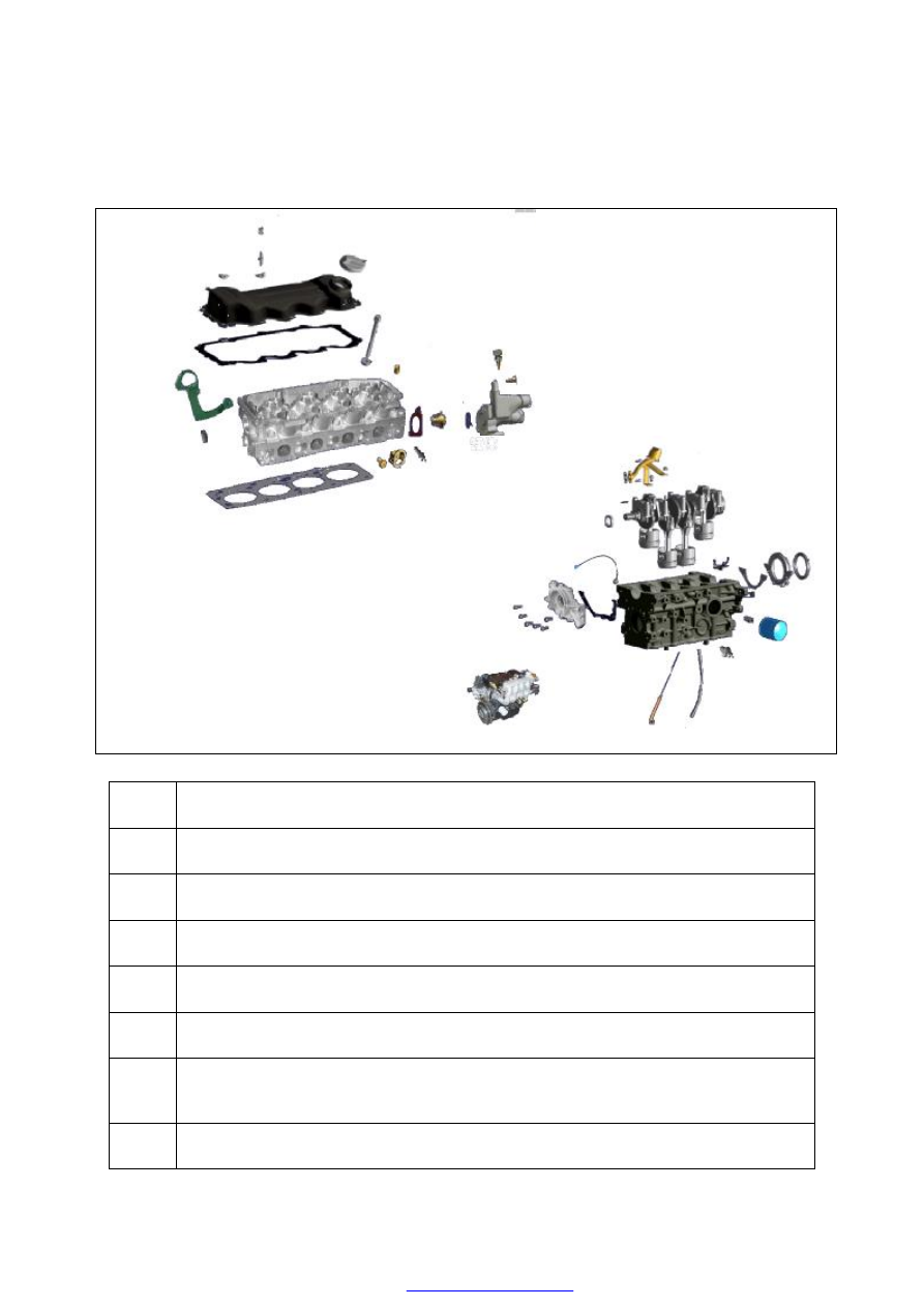
LOCATION INDEX 

  MECHANICAL LOCATION INDEX 


TIMING BELT 

(SEE A-4 ENGINE TIMING) 

VALVE MECHANISM COMPONENTS 

(SEE A-9 VALVE CLEARANCE) 

CYLINDER HEAD GASKET 

(SEE A-19 CYLINDER HEAD GASKET REPLACEMENT) 

FRONT OIL SEAL 

(SEE A-21 FRONT OIL SEAL REPLACEMENT) 

REAR OIL SEAL 

(SEE A-23 REAR OIL SEAL REPLACEMENT) 

CAMSHAFT 

(SEE A-25 CAMSHAFT) 

CRANKSHAFT 

(SEE  A-28  CRANKSHAFT,  CRANKSHAFT  THRUST  SPACER,  BEARING  SHELL  AND 
MAIN BEARING CAP) 

PISTON AND CONNECTING ROD 

(SEE A-33 PISTON AND CONNECTING ROD ASSEMBLY) 


TOP AND BOTTOM TIMING GEAR 
COVER ASSEMBLY
 

Removal 

Loosen  and  unscrew  two  bolts  of  the top  timing 
gear cover assembly.   

Remove  the  top  timing  gear  cover  and


gasket 

assembly. 

Remove  the  gasket  from  the  top  timing  gear 
cover. 

Remove the crank pulley. 

Loosen  and  unscrew  the  two  bolts  on  the timing 
gear cover. 

Remove  the  timing  gear  cover  and  gasket 
assembly. 

Remove  the  gasket  from  the  bottom  timing  gear 
cover. 


Installation 

Clean  the  bottom  timing  gear  cover  and  fix  the 
new gasket on the bottom timing gear cover with 
glue.  Install  the  bottom  timing  gear  cover  and 
gasket assembly on the crank shaft, screw in two 
bolts by hands and tighten them for a moment of 
9.0~11N.m. 

Clean the top timing gear cover and fix the new 
gasket on the top timing gear cover with glue. Fix 
the top timing gear cover and gasket assembly on 
the cylinder head with two bolts for a tightening 
moment of 9~11N.m. 


TIMING BELT REMOVAL 

 
Rotate  the  crank  shaft  to  the  compression  TDC 
on the first cylinder. Loosen the two bolts on the 
tension  pulley  (as  indicated  by  the  arrows  in  the 
figure)  and  push  the  tension  pulley  towards  one 
side  by  a  large-size  screwdriver  to  release  the 
belt tension.   


ENGINE TIMING


Note:  After  the  belt  is  taken  out,  do  not  rotate 

the  gear  to  a  large  extent,  otherwise  the 
piston head and the valve will be damaged 
due  to  collision.  To  continue  using  the 
removed  belt,  carefully  check  whether 
there  is  abnormal  abrasion,  stratified 
cracks  (especially  those  around  the  root) 
or  fouling  on  the  belt.  Replace  it 
immediately even if the slightest suspicion 
exists. 


TIMING BELT INSTALLATION AND 
ALIGNMENT 

Check  whether  the  crank  shaft  is  in  the  TDC 
position  for  the  first  cylinder.  If  necessary, 
slightly  rotate  the  crank  shaft  for  alignment  and 
lock  it  around  the  flywheel  ring  gear.  Make  the 
tooth  of  the  timing  belt  and  the  gullet  of  the 
flywheel  in  gear  and  drag the  belt  to the right  in 
an  upward  vertical  direction  to  enable  it  to 
engage with the cam gear and slot.   

When installing the old belt, be sure to keep the 
original direction of movement and engage it with 
the original engaging teeth. After the belt is in 
place, check it and be sure that the positions of 
two gears haven’t been changed. 


Carefully  coil  the  belt  around  the  tension  pulley 
to  enable  it  to  engage  with    water  pump  gear. 
Check  it again to ensure that the positions of the 
two teeth haven’t been changed.   

Loosen the two fixing bolts of the tension pulley 
to  try  to  push  it  to  the  right  (seeing  from  the 
direction  of  pulley)  as  possible,  tighten  its  two 
fixing  bolts  and  loosen  the  locking  device of the 
crankshaft. 

Rotate the crankshaft clockwise (seeing  from the 
direction  of  pulley)  for  two  circles  to  the 
compression TDC position on the first cylinder. 


Hold  the  middle  of  the  right  belt  that  is  away 
from both the crankshaft gear and camshaft gear 
with the thumb and the first finger. If the tension 
of  the  belt  is  up  to  standard,  the  belt  shall  be 
able to twist at 90°at this point. 


To adjust the tension of the belt,  loosen the two 
fixing  bolts  of  the  tension  pulley,  push  the 
tension pulley to the right with a screwdriver as 
a  ram,  then  fasten  the  fixing  bolts  again,  rotate 
the  crank  shaft  and  check  the  tension  again. 
Right  tension  may  be  obtained  after  2~3 
adjustments.  Fasten  the  tension  pulley  with 
fixing  bolts for a moment of 16-20N. after such 
adjustments are completed. 


Key 

Bush 

Bolt: M12*1.5*30 
Tightening torque: 52~60Nm 

Key 

Bolt: M8*25 

Tightening torque: 16~20Nm 

Tension Pulley 

Crankshaft Gear 

Timing gear 


Content   ..  27  28  29  30   ..