Chery A15. Manual - part 295
 

  Index      Chery     Chery A15 - service repair manual


Search            


Content   ..  293  294  295 


Chery A15. Manual - part 295


IV. Output shaft bearing and lining 


1. Unfixing 
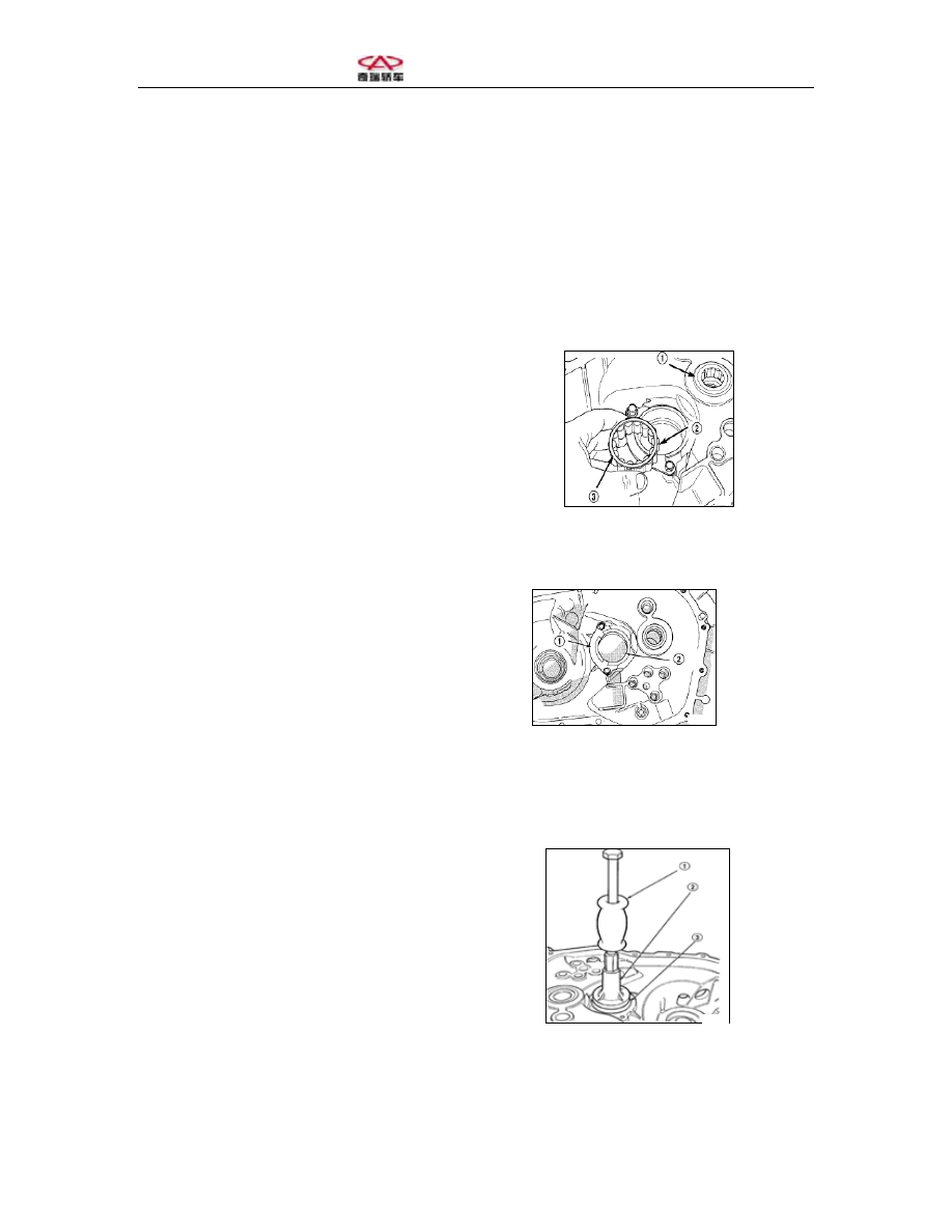
(1) Unfix the needle roller bearing from the output shaft bearing ring (Figure 135). 
(2) Unfix the output shaft bearing spacer plate bolts (Figure 136). 
(3) Fasten fix Tool 6787 and screw the special tools onto the output shaft bearing ring 
(Figure 137). 
(4) Unfix output shaft bearing ring with special tools.  


1-Input shaft bearing 
2-Output shaft bearing 
3-Big-diameter retainer ring 


1-Bearing spacer plate 
2-Bearing seat washer 


1-C-3752 
2-Special Tool 6787 
3-Output shaft bearing 


Figure 135 Output Shaft Bearing 


Figure 136 Output Shaft Bearing 


Figure 137 Unfixing the Output Shaft 
Bearing Lining 


2. Fixing 
(1) Place the output shaft bearing into 
the hole of the bearing seat washer 
 
(2) Insert Special Tool C-4628 and C-
4171 into output shaft bearing seat 
washer (Figure 138).  
The screwing torque is 11N.m (96in.lbs). 


1-Tool C-4171 
2-Tool C-4628 
3-Output shaft bearing seat washer 


V. Unfixing the synchronizer 
1. Cleaning synchronizer 
Clean the synchronizer with cloth and 
take out the spring, steel balls, sliding 
blocks and couplings carefully.  
2. Cleaning spring assembly 
Do not try clearing the spring and 
assembly with cloth as the friction parts 
will peel off. Blow it clean with 
compressed air.  
3. Checking 
Check the following components:  
Deformed, worn-out and defected tooth 
Worn-out or deformed spline 
Deformed and worn-out steel balls and 
springs 
Please replace the assembly in the above 
cases.  
4. Assembly 
(1) Fix proper synchronizer spline hub 
onto the input shaft with the “U”-marked 
side of the spline hub facing upwards.  


Figure 138 Fixing the Output Shaft 
Bearing Seat Washer 


(2) Fix the spring onto the spline hub 
(Figure 139). 
 
1-Coupling 
2-Steel ball 
3-Sliding block 
4-Spring 
5-Spline hub 


(3) Fix the sliding block and spring onto 
the spline hub.  
(4) Apply lubricating oil onto the sliding 
block and fix the steel balls onto the 
sliding block (Figure 140). 
 
1-Output shaft 
2-Spline hub 
3-Sliding block 
4-Steel ball 


(5) Press down the steel ball sliding 
block coupling and fix the coupling in 
place (Figure 141). 


1-Coupling 
2-Input shaft 
3-Sliding block 


Figure 139 Synchronizer Assembly 


Figure 140 Synchronizer Steel Balls 


Figure 141 Coupling the Synchronizer 


(6) Place the synchronizing ring onto the 
spline (Figure 142). 


(7) Fix the synchronizing ring. The 
spline and steel ball are required to be 
fixed into the synchronizing ring.  


1- Synchronizing ring 
2-Synchronizer 
3-Sliding block 
4-Steel ball 
5-Spring 


Figure 142 Sliding Block 


Content   ..  293  294  295