Chery A15. Manual - part 206


  Index      Chery     Chery A15 - service repair manual


Search            


Content   ..  204  205  206  207   ..


Chery A15. Manual - part 206


  Chery A15 Maintenance Manual  


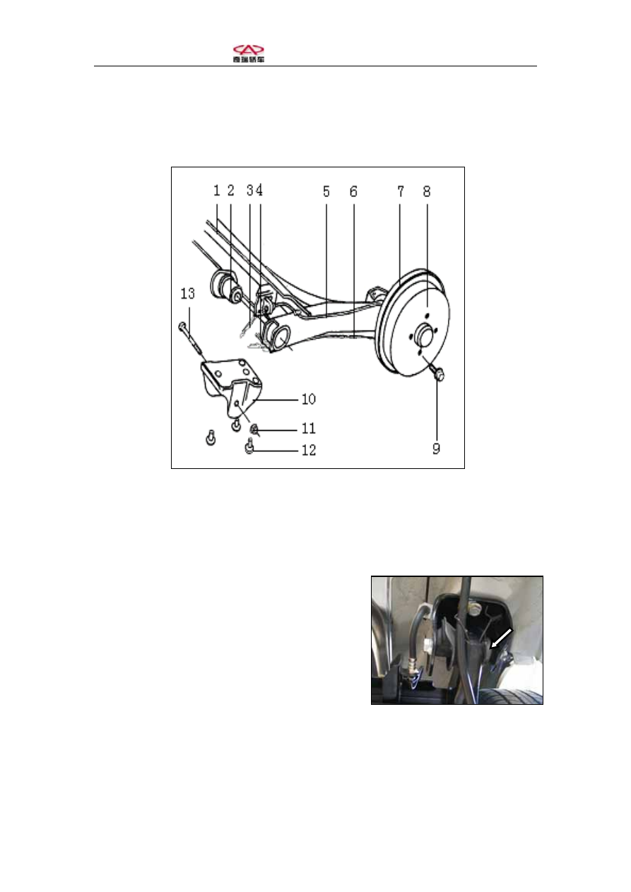
I. Structure of Rear Axle Assembly 


Figure: Rear Axle Assembly 

1. Rear axle welded assembly        2. Metal rubber bearer        3. Rear brake hose 
4. Hand brake dragline lock thread        5. Rear axle left brake line assembly 
6. Hand brake dragline    7. Brake   8. Brake drum    9. Tire fastening bolt (110Nm) 
10. Rear axle bracket    11. Nut (60Nm)    12. Bolt (70Nm) 


(I). Structure of Rear Axle Assembly 

(as shown in the figure) 

(II). Assembling Rear Axle Assembly 

1. Fixing metal rubber bearer: press the metal   

rubber bearer 2 into the axle, and keep pressing 

it until the edge reaches solid axle. 

2. Connect two rear axle brackets with bolt 13   

through the center hole in metal rubber bearer,   

standard tightening torque of nut is 60Nm;   

(as shown in the figure) 

  Chery A15 Maintenance Manual  

3. Assemble brake, brake drum and half rear axle; 

4. Connect left and right brake line assemblies   

respectively to left and right brake assembly,   

and fix them onto rear axle with pipe fixing   

clips, meanwhile connect leaf spring with rear 

brake hose through rear axle brackets.   

Tightening torque: 13-19Nm; (as shown in the figure) 


5. Fix the hand brake dragline with bracket   

clamp and the brake dragline lock thread attached 

on rear axle. 


II. Rear Shock Absorber Assembly 

(I). Structure of Rear Shock Absorber Assembly: 


  Chery A15 Maintenance Manual  


Figure: Rear Shock Absorber Assembly 

1. Thin hexagon nut, 15Nm        2. Rear sliding post upper cover        3. Disk washer 
4. Thin hexagon nut, 15Nm        5. Rubber bracket II        6. Bearing sleeve 
7. Rear spring upper base        8. Locating ring        9. Rear spring upper pad 
10. Rear bumper    11. Dustcover    12. Protection cap     
13. Rear shock absorber assembly    14. Rear helical spring      15. Rear spring lower disk
16. Lower disk bearing pad        17. Bowl washer        18. Rubber bearing block I     
19. Bearer disk    20. Thin hexagon nut, 25Nm    21. Bolt    22. Nut, 70Nm 

(II). Assembling Rear Shock Absorber Assembly (refer to figure: Rear Shock 

Absorber Assembly) 

1. Fit rear spring lower disk 15 on rear shock absorber assembly 13 and press to fix it 

with a force of 9.5-10KN, and then fit lower disk bracket and press to fit with a force 

of 2-3KN after mounting the lower disc bearing pad; 

2. Fit in turn rear helical spring 14 and protection cap 12 on rear shock absorber 

piston rod, and then the assembled rear bumper 10 and dustcover 11; 

3. Compress rear helical spring 14 to 280-300mm, and then fix locating ring 8, rear 

spring upper pad 9, rear spring upper base 7, bearing sleeve 6 and rubber bearing 

block II 5, then tighten thin hexagon nut 4 to specified torque (15Nm); 

(III) Assembling Shock Absorber Spring 

1). As shown in the figure below, hole a must be aligned with the bush of connecting 

sleeve 2 when assembling rear spring lower disk, otherwise spring disk 1 will collide 

with tire under the extreme running condition. 

2) Pay attention to the position of rear spring upper pad when assembling, as shown 

in the figure. 


a

Figure: Mounting Position of Spring Base          Figure: Mounting Position of

Spring Lower Disk

  Chery A15 Maintenance Manual  


III. Installing Rear Shock Absorber Assembly (refer to Figure: Rear 

Shock Absorber Assembly) 

1. Fit the rear shock absorber assembly upward from 

the bottom of vehicle body to extrude the piston   

rod into passenger compartment through   

shock absorber base;   

2. Fit in turn bowl washer 17, rubber bearing block 18   

and bearer disk 19 on piston rod in the passenger   

compartment, and then tighten thin hexagon nut 20 

to 25Nm. 


3. Lift the car, insert the shock absorber connecting   

sleeve in the corresponding position in the rear   

axle assembly, and tighten with bolt 21 and nut 22 

to specified torque (70Nm).   

(As shown in the figure) 


4. Fix tire and lay down the car to tighten thin   

hexagon nut 20 to specified torque (25Nm). 

5. Fit on bowl washer 3, and tighten thin hexagon 

nut 1 to specified torque (15Nm). 

6. Assemble rear shock absorber upper cover 2 to 

prevent dusts and sundries from entering and   

causing abnormal wearing of piston rod.   

(As shown in the figure) 


Content   ..  204  205  206  207   ..