Chery A15. Manual - part 162


  Index      Chery     Chery A15 - service repair manual


Search            


Content   ..  160  161  162  163   ..


Chery A15. Manual - part 162


  Chery A15 Maintenance Manual 

90º. The current intensity passing through coils changes with ohmic value of sensor, 

therefore the magnetic flux produced by coils in four directions change 

correspondingly to rotate magnetic spindle and move gauge pointer. 


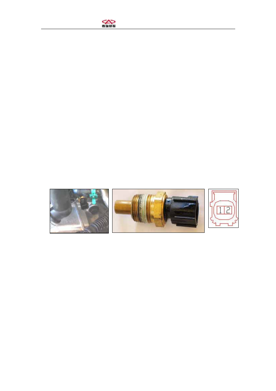
3. Function and Principle of Water Temperature Sensor 

Chery A15 adopts a thermal resistance water temperature sensor, as shown in the 

figure. 

Coolant temperature sensor serves to measure working temperature of engine, while 

ECM provides optimal arrangement of controls according to different temperatures. 

Coolant temperature sensor adopts a negative temperature coefficient resistor as the 

sensing element; 

Terminals: 1-signal grounding, 2-Temperature signal 

Installation: Coolant temperature sensor is fixed on coolant lesser circulation passage 

behind the engine. 


4. Parameters 

Working voltage: 5V DC 

Working temperature: -40~135C 

Resistance: 3560~2260 

Ω under normal temperature 20~30ºC 

Thermal resistance is made of semiconductor material with negative temperature 

coefficient, whose ohmic value sharply declines with the increase in temperature. 

Water temperature sensor is serially connected with cross coils in water temperature 

gauge. When engine coolant temperature increases, ohmic value of water temperature 

sensor decreases, the current passing through cross coils consequentially increases, 

and the deflection angle of gauge pointer becomes larger. Contrarily, when engine 

  Chery A15 Maintenance Manual 

coolant temperature increases, the deflection angle of water temperature gauge pointer 

becomes smaller. 


5. Fuel Gauge 

Working condition of fuel gauge is basically the same with water temperature gauge, 

and it adopts a cross coil pointer meter, too. As the figure shows (Meter-5), the right 

part of the meter is the fuel gauge. 


Fuel Gauge (Meter-5)


When floater moves with the level change in fuel tank, the sliding contact linked with 

floater rod corresponds to change the ohmic value of thick-film resistor. When the 

fuel tank is filled, the ohmic value of thick-film resistor is the minimum, while the 

current of cross coils is the maximum, and the fuel gauge pointer points to the 

maximum scale mark F. On the contrary, when fuel tank is empty, the ohmic value of 

thick-film resistor is the maximum, and fuel gauge pointer points to the scale mark E 

with the minimum angle of deflection. 

Relationship between fuel level and ohmic value is shown in the table below. 

Relationship between Fuel Level and Ohmic Value 

Floater Position 

Volume (L) 

Resistance (Ω) 

Empty 0 283 

1/2 30 

89 

Full 55 

36 


  Chery A15 Maintenance Manual 


Section Three: Troubleshooting 

Component Symptom 

Possible 

Cause Solution 

Remarks

Speedometer 

Speedometer 

does not 

work when 

vehicle is 

running or 

indicates 

with notable 

discrepancy 

with actual 

speed 

(1) Hall speed sensor 

defect. 

(2) Pointer stuck. 

(3) Worn-out driving 

gear of transmission 

output shaft or 

oversize gear 

backlash. 

(4) Speedometer 

damage. 

(5) Engine damage. 

(6) Wire connection 

fault. 

(1) In case the speedometer dose 

not work, first check Hall speed 

sensor and engagement of driving 

gear, if normal then check 

speedometer.  

(2) Single symptom of inaccurate 

indication is generally caused by 

internal breakdown. 

(3) Check connection between 

speed signal and engine, and 

signal wire between engine and 

speedometer. 


Water 

temperature 

gauge 

Water 

temperature 

gauge has no 

indication 

after engine 

is started 

(1) Water temperature 

gauge damage. 

(2) Water temperature 

sensor failure. 

(3) Open circuit of 

water temperature 

gauge. 

(4) Voltage stabilizer 

damage. 

(5) Engine computer 

damage. 

(1) Open engine hood and unplug 

water temperature sensor to check 

sensor resistance, if normal then 

check signal wires between sensor 

and engine computer and between 

engine computer and the gauge. 

(2) If all the wires are normal, 

plug in combination instrument 

and turn on ignition switch to 

check if the yellow/red wire of 

water temperature sensor is 

conducted. If yes, the water 

temperature sensor is damaged; 

and if no, the water temperature 

gauge or voltage stabilizer is 

damaged. 

(3) Demount dashboard with wire 

harnesses still connected, connect 

a multimeter between anode 

terminal 1 and earthing terminal 2 

of voltage stabilizer to measure 

voltage. If the measured value is 


  Chery A15 Maintenance Manual 

higher than 10.5V or lower than 

9.5V, the voltage stabilizer 

probably has fault, otherwise it 

should be the problem with water 

temperature gauge itself. 

Fuel gauge 

Fuel gauge 

pointer does 

not move 

after ignition 

switch is 

turned on 

(1) Fuel gauge 

damage. 

(2) Fuel gauge sensor 

failure. 

(3) Open circuit of 

fuel gauge. 

(4) Voltage stabilizer 

damage. 

(5) Fuel tank emptied.

(1) Check if fuel tank is empty. 

(2) Turn on ignition switch to see 

if water temperature gauge is 

working. If yes, the voltage 

stabilizer of combination 

instrument is normal. 

3)Unplug fuel gauge sensor 

and measure purple/black wire 

with a multimeter to see if it is 

conducted, and then check the 

earthing between brown wire and 

vehicle body. If purple/black wire 

is conducted and brown wire is 

normal, fuel gange sensor is at 

fault and shall be replaced. 

(4) If purple/black wire is not 

conducted, check the purple/black 

wire between fuel gauge sensor 

plug and hole 21 of combination 

instrument plug for open circuit. 

Wire transfer route is as follow: 

purple/black wire of fuel gauge 

sensor plug → hole 3 of relay 

board plug M  →  hole 12 of relay 

board plug U1  → brown wire → 

hole 21 of combination instrument 

plug. 

(5) If the circuit is conducted and 

brown wire is normal, it should be 

fuel gauge fault. 

Please 

refer to 

circuit 

diagram 

of fuel 

gauge 

Engine oil 

pressure 

warning 

light 

Engine oil 

pressure 

warning 

light keeps 

(1) Low pressure 

switch (30KPa switch) 

fault. 

(2) Short circuit of low 

First identify whether it is 

lubrication system fault or 

warning system fault. This is 

usually done by measuring oil 


Content   ..  160  161  162  163   ..