Chery A15. Manual - part 142


  Index      Chery     Chery A15 - service repair manual


Search            


Content   ..  140  141  142  143   ..


Chery A15. Manual - part 142


Chapter One: Air Conditioning System 


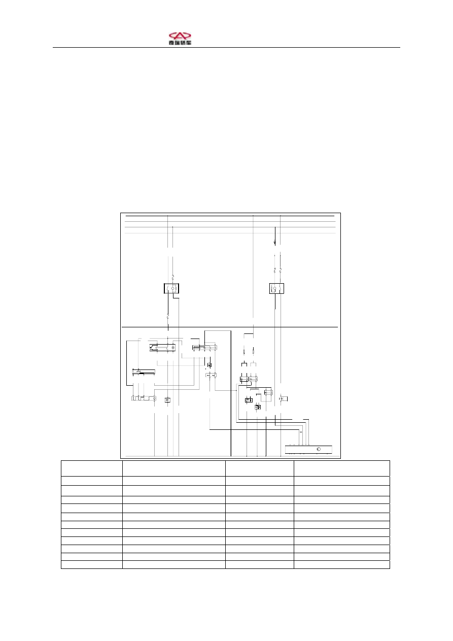
Section One: Circuit Diagram of Air Conditioning System 

Instructions 

30 has no fuse, with positive pole directly connected to battery 
15 has no fuse, with positive pole connected to ignition switch   
X has no fuse, with positive pole connected to ignition switch and disconnected when 
starting 
Wire 31 is earthed. 

棕/白

低速风扇
继电器

30A

2.5

红/黑

4.0

红/黑

2.5

30A

FS
25

黑/红
2.5

0.5

2.5

8/87

6/85

2/30

4/86

红/黑

2.5

2.5

1

M

3

1.5

20

A

WIP
ER

FS
8

A3

A2

E4

5

12
V

85

86
2

空调泵继

电器

1

30

87

3

FS
1

15

A

CO
MP

E8

TQ3/8

TQ2/11

2.5

2.5

红/兰

红/黑
1.5

1.5

8

67 2

1

J200

0

空调泵

发动机电脑

灰/白

0.5

棕/绿
1.0

绿/黄

1.0

 棕
2.5

5

N23

1

2

E9

5

白/黑

1.0

1.5

4

4

M

3

绿

2.5

1

黄/红

1.5

2

黑/红
2.5

 白/黑
1.0

黑/红
2.5

绿/黄

0.5


0.5

V2

N63

5

6

白/绿

1.0

1

0.5

2

黑/红

2.5

0.5

3

4

2

1

黄/红

1.5

3

2.5

8

2

1

白/绿

1.0

1

4

7

1.0

4

3

2

5

6

30
A

B4

R/
SC

K

FS
9

10
A

FS
12

IMM
O

E1
2

D1
3

D1
2

2.5

红/兰

2.5

1.0

NR
0.5

85

12

V

86

机继电器

30

87

空调开关

空调继电器

温度

传感器

空调压力

开关

鼓风机开关

鼓风机

电阻

30

15

X

31

31

鼓风
机电

红/

2.5

6/85

J71

4/86

8/87

2/30

V8

2

0.5

1

3

V7

M

黑/红

4.0

2.5

红/白

2.5

4.0

0.5

红/

2.5

FS
25

隔离继电器

内外循
环电磁

高速风扇

继电器

离合器

4/86 2/30

6/85 8/87

散热
风扇

散热
风扇


鼓风机继电器 Blower 

relay 

内外循环电磁阀 

Internal/external circulating 
electromagnetic valve 

空调泵继电器 

Air conditioning pump relay 

散热风扇 Cooling 

fan 

空调继电器 

Air conditioner relay 

空调泵离合器 

Air conditioning pump clutch 

空调开关 

Air conditioner switch 

发动机电脑 Engine 

computer 

鼓风机开关 Blower 

switch 

红 Red 

温度传感器 Temperature 

sensor 

兰 Blue 

空调压力开关 

Air conditioning pressure switch 

黑 Black 

高速风扇继电器 

High-speed fan relay 

白 White 

低速风扇继电器 

Low-speed fan relay 

绿 Green 

隔离继电器 Isolating 

relay 

棕 Brown 

鼓风机电阻 Blower 

resistance 

黄 Yellow 

鼓风机电机 Blower 

motor 

灰 Gray 


Section Two: Compressor Circuit 


I. Working Conditions of Compressor 

Air conditioning switch is pressed down (A/C switch); 

Blower is working; 

Cooling system pressure is open at low-pressure side; 

Ambient temperature is above 0ºC; 

Engine speed is over 600RPM. 


棕/白

1.5

20

A

WI

PER

FS

8

A3

A2

E4

5

12

V

85

86

2

空调泵继

电器

1

30

87

3

FS

1

15

A

CO

MP

E8

TQ3/8

TQ2/11

2.5

2.5

红/兰

红/黑
1.5

1.5

8

32

18

55 31

67

2058

2

9 57

46

1

J200

62

5
0

38

48

59

11

空调泵

发动机电脑

灰/白

0.5

30

15

X

31

31

高速风扇继电器85#

空调压力开关1#

低速风扇继电器85#

棕/白0.5

绿/白

1.5

灰/白0.5


低速风扇继电器 85# 

Low-speed fan relay 85# 

黑 Black 

高速风扇继电器 85# 

High-speed fan relay 85# 

棕 Brown 

空调压力开关 1# 

Air conditioning pressure switch 1# 

白 White 

发动机电脑 Engine 

computer 

灰 Gray 

红 Red 

绿 Green 

兰 Blue 


II. Working Principle of Compressor 

When ignition switch is turned on, air conditioning blower relay coil is powered by wire X 

and the contact of air conditioning blower fan is closed. 

When blower switch is placed at a position other than OFF, pin 5 of blower switch is 

powered. 

When air conditioner switch is pressed down, pin 2 and pin 1 are connected to activate air 

conditioner relay. 

Battery supplies power to engine computer through air conditioner relay, evaporator 

temperature switch and low-pressure switch. 

Engine computer processes to control opening/closing of air conditioning pump relay. 

Battery supplies power through air conditioning pump relay to compressor electromagnetic 

clutch for engagement. 


Section Three: Cooling System Circuit 


I. Working Conditions of Cooling Fan 

Blower switch is placed at a range other than 0 with air conditioner switch closed and cooling 

fan working at low speed. 

Blower switch is placed at a range other than 0 with air conditioner switch closed, 

high-pressure switch closed and cooling fan working at low speed. 

30

15

X

31


高速风扇继电器 

High-speed fan relay 

发动机电脑 8# 

Engine computer 8# 

低速风扇继电器 

Low-speed fan relay 

红 Red 

空调高压开关 3# 

Air conditioning high-pressure switch 3#

黑 Black 

隔离继电器 Isolating 

relay 

白 White 

发动机电脑 1# 

Engine computer 1 

棕 Brown 

II. Working Principle of Cooling Fan 

When engine water temperature exceeds 98ºC, water temperature sensor sends signal to 

engine computer, and engine computer activates low-speed fan relay. Battery supplies power 

to fan motor through low-speed fan relay and fan motor speed-regulating resistor. When 

engine water temperature exceeds 105ºC, water temperature sensor sends signal to engine 

computer, and engine computer activates high-speed fan relay. Battery supplies power to fan 

motor V7 through high-speed fan relay and fan motor V8 through isolating relay. 

When A/C switch is pressed down, the blower is started, and blower switch supplies power to 

air conditioner switch to activate air conditioner relay. Air conditioner relay sends earthing 

signal to engine computer through evaporator temperature sensor and air conditioning 

pressure switch, and engine computer activates low-speed fan relay. Battery supplies power to 

fan motor through relay and fan motor speed-regulating resistor. 


Content   ..  140  141  142  143   ..