Chery A15. Manual - part 120


  Index      Chery     Chery A15 - service repair manual


Search            


Content   ..  118  119  120  121   ..


Chery A15. Manual - part 120


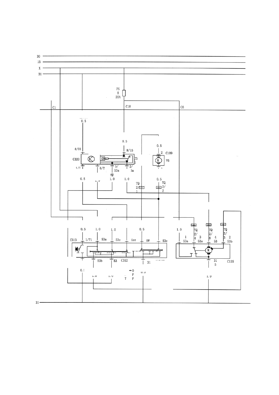
The circuit schematic diagram of the front window wiper and washer of Chery sedan A15: 


wiper switch 

wiper motor

brown and yellow 

black and gray

blown

horn  
button 

green and black 

black and gray 

blown

black and blue

green and black

green 

and yellow 

blown and blue 

black and gray

green

green 

green and red 

washer 

green

green and red 

glay and black 

Intermittent wiper relay

black and blue 

black and blue 

blown and black 

to horn relay 

The circuit schematic diagram of the front window wiper and washer.


T-37


The working list of wiper/washer components 

Gear 

Intermittent 

wiper relay 

(state of 

conduction 

between the 

pins) 

V5 washer 

(state of 

conduction 

between the 

pins) 

Wiper switch 

(state of 

conduction 

between the 

pins) 

Wiper motor 

(state of 

conduction 

between the 

pins) 

Remarks

Low gear 

5/53s 

2/53m 

B+ 


53e 

53 

B+ 

53 

B+ 

B+ 

(power 

supply 

positive 

grid) 

High gear 


53b 

53a 

B+ 

53b 

B+ 

B+ 

(power 

supply 

positive 

grid) 

Intermittent 

gear 

1/J 

2/53m 

B+ 

8/15 


int 

53a 

B+ 

53 

B+ 

B+ 

(power 

supply 

positive 

grid) 

Reset gear 

5/53s 

2/53m 

B+ 


53 

53e 

B+ 

53 

53e 
53a 

B+ 

B+ 

(power 

supply 

positive 

grid) 

Washing 

gear 

6/T 

2/53m 

8/15 

B+ 

B+ 


53a 
53c 

B+ 

53 

B+ 

B+ 

(power 

supply 

positive 

grid) 


REMOVAL/INSTALLATION OF WIPER WASHER SYSTEM


1. INSTALLATION/REMOVAL OF THE WIPER SYSTEM: 

z Disconnect the negative grid of the battery; 

z Assemble the wiper blade and wiper arm; 

z Open the front hood; 


T-38


z Place the wiper link-rod inside and concentric the fastening hole with the welded nut of car 
body; 

z Tighten it with 3 bolts and washers, and the tightening torque is 9N·m; 

z Install the water channel guard for the front window and other parts (see car body 

instruction for details); 

z According to the arrow printed on the front window, align the wiper blade with the 

assembling arrow on the window; place the wiper arm into the wiper arm shaft, tighten the 
fastening nut of the wiper arm and in the mean time press the blade tightly without 
moving; 

z Tighten the wiper arm with 2 nuts with tightening torque of 16~19 Nm, and install the 
guard plate. 

z The installing steps are reverse to those for removal. 

2. INSTALLATION/REMOVAL OF THE WASHER SYSTEM 

z Install 6 fastening clips of the washing liquid tube and 1 guard sleeve;   

z Install the nozzle on the front hood; 

z Insert one end of the washing liquid tube into the washing liquid container, install the 

washing liquid tube in the correct direction and insert the connector to the nozzle properly;   

z Align the washing liquid container with the stationery jaw of car body, and tighten it with 1 

nut and washer. 

z The installing steps are reverse to those for removal. 


FAULT DIAGNOSIS AND TROUBLESHOOTING 

Functioning 

state of the 

component 

Malfunction 

symptom 

Malfunction 

reasons 

Malfunction 

diagnosis and 

troubleshooting 

Remarks

The wiper motor 
does not 
function. 

When the 
ignition switch 
is turned on, turn 
the wiper switch 
to (intermittent 
wiping), (slow 
wiping), (fast 
wiping), 
(short-time 
wiping) position, 
the wiper motor 
always does not 
function. 

(1) The power 
supply circuit of 
the wiper motor 
is open. 
(2) Poor contact 
of the ignition 
switch and the 
wiper switch. 
(3) There is an 
open circuited 
point in the 
wiper motor. 
 

(1) Check the circuit 
of the wiper power to 
see whether there is 
any open circuit. If 
there is, fix it 
immediately. 
(2) Test the voltage of 
each point of the 
motor winding with 
multimeter, and verify 
that the motor circuit 
is open. If it is open, 
replace the motor. 


T-39


(3) Verify that the 
wiper switch and the 
X-contact off-load 
relay function 
normally. Otherwise, 
replace the 
corresponding parts. 

The intermittent 
wiping does not 
function. 

When the 
ignition switch 
is turned on, turn 
the wiper switch 
to (intermittent 
wiping) position, 
the wiper motor 
does not 
function 
intermittently. 

(1) The circuit 
of the wiper 
intermittent 
controller is 
open. 
(2) The internal 
part of the wiper 
intermittent 
controller is 
damaged. 
 

(1) Verify that the fuse 
S8 in the relay box and 
the wiper relay, 
8/15-contact off-load 
relay are normal. 
(2) If the fuse and the 
relay are normal, 
verify that whether the 
intermittent controller 
circuit of the wiper is 
open. 
The route of the circuit 
is as follows: 
Turn on the ignition 
switch 

→ wiper motor 

terminal 5F/2 

→ turn 

on the intermittent 
gear -5F/5 

→ 

intermittent controller 
relay 1/J 

→ 

intermittent controller 
relay function. 
Fuse S8 → wiper relay 
terminal 8/15 → wiper 
relay terminal 2/53M 
→ the 2# socket of the 
relay base connector S 
→ green wire → wiper 
motor terminal 4/53 → 
wiper motor terminal 
5/31  → brown/yellow 
wire → grounding. 
(3) If the circuit works 
properly, it is the 
malfunction of wiper 
intermittent controller. 


T-40


Content   ..  118  119  120  121   ..